Chapter: Computer Architecture : Overview & Instructions
Computer Architecture: Addressing and Addressing Modes
ADDRESSING AND ADDRESSING MODES
To perform any operation, the
corresponding instruction is to be given to the microprocessor. In each
instruction, programmer has to specify 3 things:
·
Operation to be performed.
·
Address of source of data.
·
Address of destination of result.
Definition:
·
The different ways in which the location of an
operand is specified in an instruction are referred to as addressing modes.
· The
method by which the address of source of data or the address of destination of
result is given in the instruction is called Addressing Modes
· Computers
use addressing mode techniques for the purpose of accommodating one or both of
the following provisions:
·
To give programming versatility to the user by
providing such facilities as pointers to memory, counters for loop control,
indexing of data, and program relocation.
·
To reduce the number of bits in the addressing
field of the instruction.
IMPLEMENTATION OF VARIABLES AND CONSTANTS
Variables and constants are the
simplest data types and are found in almost every computer program. A variable
is represented by allocating a register or a memory location to hold its value.
Thus, the value can be changed as needed using appropriate instructions.
1. Register
addressing mode - The operand is the contents of a processor
register; the name (address) of the register is given in the instruction.
Example: MOVE R1,R2
This instruction copies the
contents of register R2 to R1.
2.
Absolute addressing mode - The
operand is in a memory location; the address of this location is given
explicitly in the instruction. (In some assembly languages, this mode is called
Direct.)
Example: MOVE LOC,R2
This instruction copies the
contents of memory location of LOC to register R2.
3. Immediate
addressing mode - The operand is given explicitly in the
instruction.
Example: MOVE #200 , R0
The above statement places the value 200 in the register R0. A
common convention is to use the sharp sign (#) in front of the value to
indicate that this value is to be used as an immediate operand.
INDIRECTION AND POINTERS
In the addressing modes that
follow, the instruction does not give the operand or its address explicitly.
Instead, it provides information from which the memory address of the operand
can be determined. We refer to this address as the effective address (EA) of
the operand.
4. Indirect addressing mode
The effective address of the
operand is the contents of a register or memory location whose address appears
in the instruction.
Example Add (R2),R0
Register R2 is used as a pointer
to the numbers in the list, and the operands are accessed indirectly through
R2. The initialization section of the program loads the counter value n from
memory location N into Rl and uses the Immediate addressing mode to place the
address value NUM 1, which is the address of the first number in the list, into
R2.
INDEXING AND ARRAY
It is useful in dealing with lists and arrays.
5. Index mode
The effective address of the
operand is generated by adding a constant value to the contents of a register.
The register used may be either a special register provided for this purpose,
or, more commonly; it may be anyone of a set of general-purpose registers in
the processor. In either case, it is referred to as an index register. We
indicate the Index mode symbolically as
X(Ri).
Where X denotes the constant
value contained in the instruction and Ri is the name of the register involved.
The effective address of the operand is given by EA = X + [Ri]. The
contents of the index register are not changed in the process of generating the
effective address.
RELATIVE ADDRESSING
An useful version of this mode is
obtained if the program counter, PC, is used instead of a general purpose
register. Then, X(PC) can be used to address a memory location that is X bytes
away from the location presently pointed to by the program counter. Since the
addressed location is identified ''relative'' to the program counter, which
always identifies the current execution point in a program, the name Relative
mode is associated with this type of addressing.
6.Relative mode - The
effective address is determined by the Index mode using the program counter
in place of the general-purpose register Ri. This mode can be used to access
data operands. But, its most common use is to specify the target address in
branch instructions. An instruction such as Branch>O LOOP causes program
execution to go to the branch target location identified by the name LOOP if
the branch condition is satisfied. This location can be computed by specifying
it as an offset from the current value of the program counter. Since the branch
target may be either before or after the branch instruction, the offset is
given as a signed number.
ADDITIONAL MODES
The two additional modes
described are useful for accessing data items in successive locations in the
memory.
7. Autoincrement
mode - The effective address of the operand is the contents of a
register specified in the instruction. After accessing the operand, the
contents of this register are automatically incremented to point to the next
item in a list. We denote the Autoincrement mode by putting the specified
register in parentheses, to show that the contents of the register are used as
the effective address, followed by a plus sign to indicate that these contents
are to be incremented after the operand is accessed. Thus, the Autoincrement
mode is written as (Ri) +. As a companion for the Autoincrement mode,
another useful mode accesses the items of a list in the reverse order:
8.
Autodecrement mode - The
contents of a register specified in the instruction is first automatically
decremented and is then used as the effective address of the operand. We denote
the Autodecrement mode by putting the specified register in parentheses,
preceded by a sign to indicate that the contents of the register are to be
decremented before being used as the effective address. Thus, we write -
(Ri)
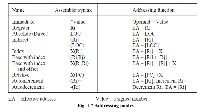
Fig. 1.7
Addressing modes
Illustration of Addressing Modes
•
Implied addressing mode
•
Immediate addressing mode
•
Direct
addressing mode
•
Indirect addressing mode
•
Register addressing mode
•
Register Indirect addressing mode
•
Autoincrement or Autodecrement addressing mode
•
Relative addressing mode
•
Indexed
addressing mode
•
Base register addressing mode
•
Implied addressing mode
In this mode the operands are
specified implicitly in the definition of the instruction. For example
the ‘complement accumulator’ instruction is an implied mode instruction because
the operand
in the accumulator register is implied in the definition of the instruction
itself. All register reference instructions that use an accumulator are implied
mode instructions. Zero address instructions in a stack organized computer are
implied mode instructions since the operands are implied to be on the top of
the stack.
Example : CMA
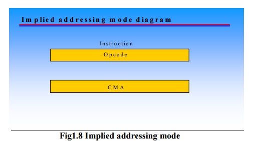
Fig1.8
Implied addressing mode
Immediate addressing mode
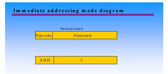
Fig. 1.9
Immediate addressing mode
In this mode the operand is
specified in the instruction itself. In other words, an immediate mode
instruction has a operand field rather than an address field. The operand field
contains the actual operand to be used in conjunction with the operation
specified in the instruction. Immediate mode instructions are useful for
initializing registers to a constant value.
Example: ADD 5
•
Add 5 to contents accumulator of
•
5 is operand
Advantages and disadvantages
•
No memory reference to fetch data
•
Fast
•
Limited range
Direct addressing mode
In this mode the effective
address is equal to the address part of the instruction. The operand resides in
memory and its address is given directly by the address field of instruction.
In a branch type instruction the address field specifies the actual branch
address
Effective
address (EA) = address field (A)
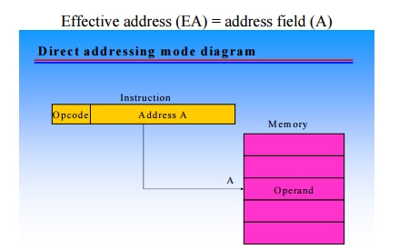
Fig. 1.10
Direct addressing mode
e.g. LDA A
Look in memory at address A for operand.
Load contents of A to accumulator
Advantages and disadvantages
•
Single memory reference to access data
•
No additional calculations to work out effective
address
•
Limited address space
Indirect addressing mode
In this mode the address field of
the instruction gives the address where the effective address is stored in
memory/register. Control fetches the instruction from memory and uses its
address part to access memory again to read the effective address.
EA =
address contained in register/memory location
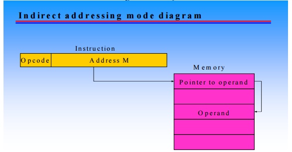
Fig. 1.11
Indirect addressing mode
Example Add (M)
•
Look in M, find address contained in M and
look there for operand
•
Add contents of memory location pointed to by
contents of M to accumulator
Register addressing mode
In this mode the operands are in the registers that reside
within the CPU.
EA = R
Example : ADD R1,R2
Advantages and disadvantages
·
No memory access. So very fast execution.
·
Very small address field needed.
·
Shorter instructions
·
Faster instruction fetch
·
Limited number of registers.
·
Multiple registers helps performance
·
Requires good assembly programming or compiler
writing
Register indirect addressing mode
In this mode the instruction
specifies a register in the CPU whose contents give the effective address of
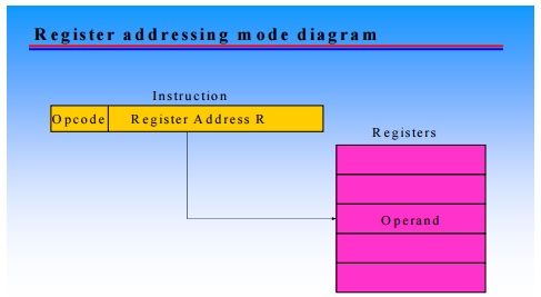
Fig.1.12
Register addressing mode
the operand in the memory. In
other words, the selected register contains the address of the operand rather
than the operand itself. Before using a register indirect mode instruction, the
programmer must ensure that the memory address of the operand is placed in the
processor register with a previous instruction. The advantage of a register
indirect mode instruction is that the address field of the instruction uses
fewer bits to select a register than would have been required to specify a
memory address directly.
Therefore EA = the address stored in the register R
•
Operand is in memory cell pointed to by contents
of register
•
Example Add (R2),R0
Advantage
•
Less number of bits are required to specify the
register.
•
One fewer memory access than indirect addressing.
Register
Indirect addressing mode diagram
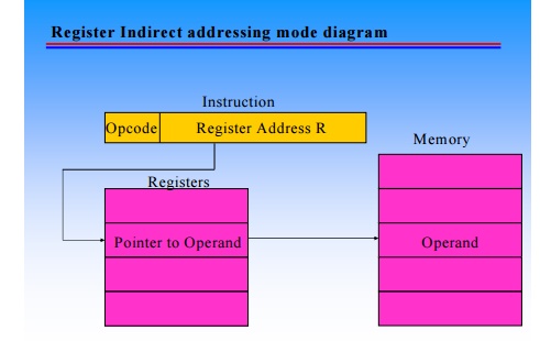
Fig. 1.13
Indirect addressing mode
Autoincrement or autodecrement addressing mode
Autoincrement mode - The
effective address of the operand is the contents of a register specified
in the instruction. After accessing the operand, the contents of this register
are automatically incremented to point to the next item in a list.
•
We denote the Autoincrement mode by putting the
specified register in parentheses, to show that the contents of the register
are used as the effective address, followed by a plus sign to indicate that
these contents are to be incremented after the operand is accessed. Thus, the
Autoincrement mode is written as (Ri) +
Autodecrement mode - The
contents of a register specified in the instruction is first automatically
decremented and is then used as the effective address of the operand.
We denote the Autodecrement mode
by putting the specified register in parentheses, preceded by a
minus sign to indicate that the
contents of the register are to be decremented before being used as the
effective address. Thus, we write - (Ri)
•
These two modes are useful when we want to access
a table of data.
ADD (R1)+
will increment the register R1.
LDA -(R1)
will
decrement the register R1.
Relative addressing mode
In this mode the content of the
program counter is added to the address part of the instruction in order to
obtain the effective address. Effective address is defined as the memory
address obtained from the computation dictated by the given addressing mode.
The address part of the instruction is usually a signed
number (in 2’s complement representation) which can be either
positive or negative. When this number is added to the content of the program
counter, the result produces an effective address whose position in memory is
relative to the address of the next instruction.
Relative addressing is often used
with branch type instructions when the branch address is in the area
surrounding the instruction word itself. It results in a shorter address field
in the instruction format since the relative address can be specified with a
smaller number of bits compared to the bits required to designate the entire
memory address.
EA = A +
contents of PC
Example: PC contains 825 and address pa rt of instruction contains 24.
After the instruction is read
from location 825, the PC is incremented to 826. So EA=826+24=850. The operand
will be found at location 850 i.e. 24 memory locations forward from the address
of the next instruction.
Fig1.14
Autoincrement and decrement addressing mode
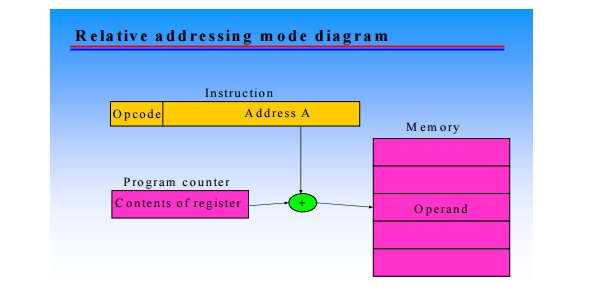
Fig.1.15
Relative addressing mode
Indexed addressing mode
In this mode the content of an
index register is added to the address part of the instruction to obtain the
effective address. The index register is a special CPU register that contains
an index value. The address field of the instruction defines the beginning
address of a data array in memory. Each operand in the array is store din
memory relative to the beginning address. The distance between the beginning
address and the address of the operand is the index value stored in the index
register. Any operand in the array can be accessed with the same instruction
provided that the index register contains the correct index value. The index register
can be incremented to facilitate access to consecutive operands. Note that if
an index type instruction does not include an address field in its format, then
the instruction converts to the register indirect mode of operation.
•
Therefore EA = A + IR
•
Example MOV AL , DS: disp [SI] Advantage
•
Good for accessing arrays.
Base register addressing mode
In this mode the content of base
register is added to the address part of the instruction to obtain the
effective address. This is similar to the indexed addressing mode except that
the register is now called a base register instead of an index register. The
difference between the two modes is in the way they are used rather than in the
way that they are computed.
An index register is assumed to
hold an index number that is relative to the address part of the instruction. A
base register is assumed to hold a base address and the address field of the
instruction gives a displacement relative to this base address. The base
register addressing mode is used in computers to facilitate the relocation of
the programs in memory. When programs and data are moved from one segment of
memory to another, as required in multiprogramming systems, the address values
of instructions must reflect this change of position. With a base
register, the displacement values
of instructions do not have to change. Only the value of the base register
requires updating to reflect the beginning of a new memory segment.
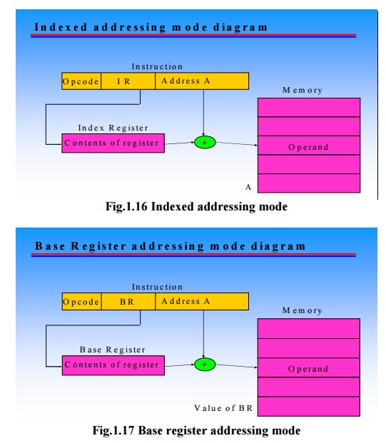
• Therefore EA= A + BR
• For example: MOV AL, disp [BX]
Segment
registers in 8086
MIPS Addressing Mode Summary
1. Immediate
addressing, where the operand is a constant within the instruction itself
2. Register
addressing, where the operand is a register
3. Base or
displacement addressing, where the operand is at the memory location whose
address is the sum of a register and a constant in the instruction
4. PC-relative
addressing, where the branch address is the sum of the PC and a constant in the
instruction
5. Pseudodirect
addressing, where the jump address is the 26 bits of the instruction
concatenated with the upper bits of the PC
Related Topics