Chapter: Electrical Engineering and Instrumentation : DC Machines
Characteristics of DC Generators
Characteristics of DC Generators
The magnetic field in a d.c. g enerator is normally produced by electromag nets rather than permanent magnets. Generators are generally classified according to their methods of field excitation. On this basis, d.c. gen erators are divided into the following two classes:
(i) Separately excited d.c. generators
(ii) Self-excited d.c. generators
The behavior of a d.c. generator on load depends upon the method of field excitation adopted.
There are two characteristics
1. Magnetic (no load or open ciircuit) characteristics
This curve shows the relation b etween the generated e.m.f. at no-load (E0) and the field current (If) at constant speed. It is also k nown as magnetic characteristic or no-load saturation curve. Its shape is practically the same fo r all generators whether separately or self-excited. The data for O.C.C. curve are obtained experimentally by operating the generator at no l oad and constant speed and recording the change in terminal voltage as the field current is varied.
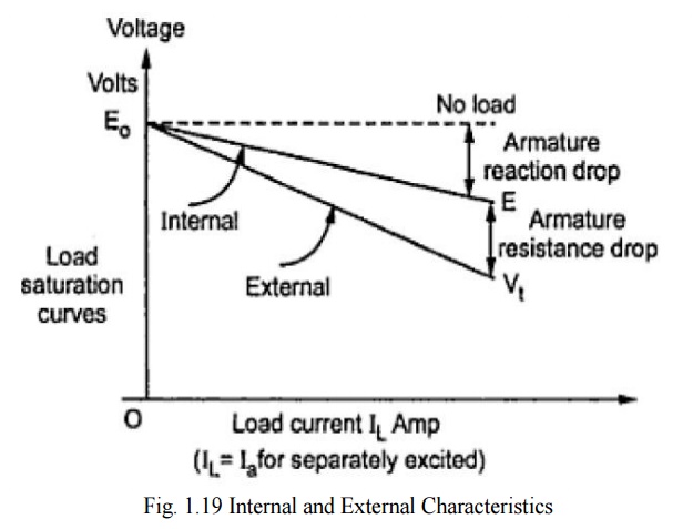
2. Internal and External characteristics
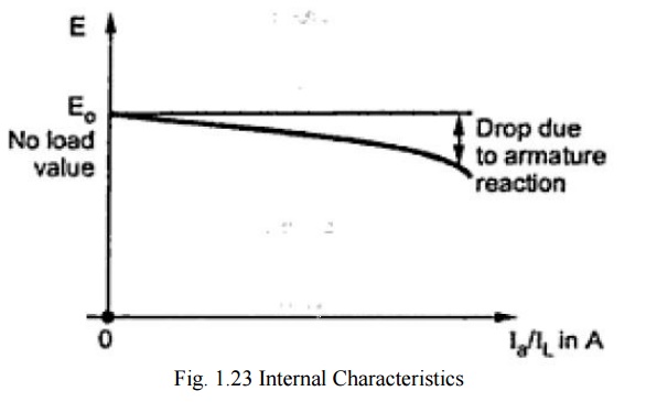
Internal characteristics
This curve shows the relation b etween the generated e.m.f. on load (E or Eg) and the armature current (Ia). The e.m.f. E is les s than E0 due to the demagnetizing effect of armature reaction. Therefore, this curve will lie below the open circuit characteristic (O.C.C .). The internal characteristic is of interest chiefly to the designer. It cannot be obtained directly by experiment. It is because a voltmeter cannot read the e.m.f. generated on load due to the voltage drop in armature resistance. The internaal characteristic can be obtained from external characteristic if winding resistances are know n because armature reaction effect is in cluded in both characteristics
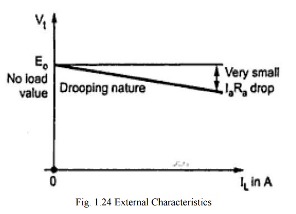
External characteristics
This curve shows the relation between the terminal voltage (Vt) and load current (IL). The terminal voltageVt will be less than E due to voltage drop in the armature circu it. Therefore, this curve will lie below the internal characteristic. This characteristic is very important in determining the suitability of a generator for a given purpose. It can be obtained by making simultaneous
(i) Separately Excited D.C. Generators
A d.c. generator whose field magnet winding is supplied from an independent external d.c. source (e.g., a battery etc.) is called a separately excited generator. The connections of a separately excited generator are shown below. The voltage output depends upon the speed of rotation of armature and the field current. The greater the speed and field current, greater is the generated e.m.f. It may be noted that separately excited d.c. generators are rarely used in practice. The d.c. generators are normally of self-excited type.
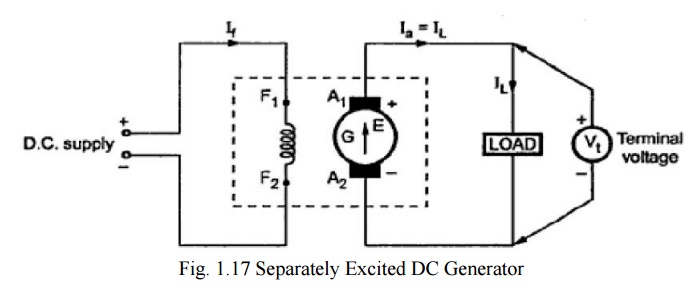
Armature current, Ia = IL
Terminal voltage, Vt = Eg – IaRa
Electric power developed = EgIa
Power delivered to load = VIL
Magnetic characteristics (E0 versus If)
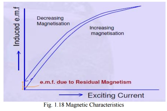
A separate excitation is normally used for testing of d.c. generators to determine their open circuit or magnetization characteristic. The excitation current is increased monotonically to a maximum value and then decreased in the same manner, while noting the terminal voltage of the armature. The load current is kept zero. The speed of the generator is held at a constant value.
The graph showing the nature of variation of the induced emf as a function of the excitation current is called as open circuit characteristic (occ), or no-load magnetization curve or no-load saturation characteristic.
Internal and External characteristics
(ii) Self-excited D.C. Generators
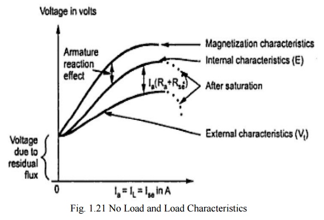
a) D.C. Series Generator
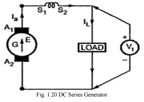
Armature current, Ia = Ise = IL Terminal voltage, Vt = Eg - Ia(Ra + Rse)
Power developed in armature = EgIa
Power delivered to load = VIa or VIL
No load and Load Characteristics
b) D.C. Shunt Generator
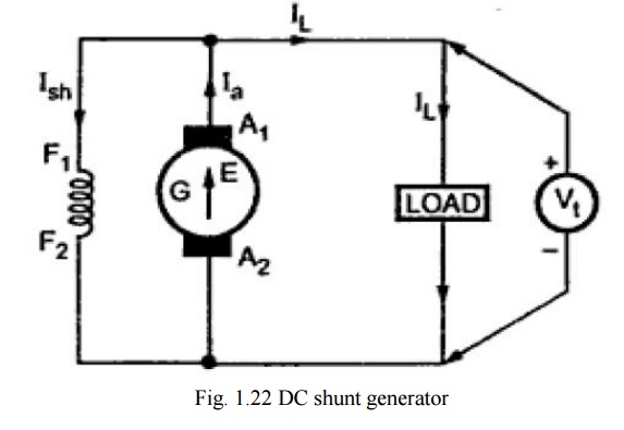
Shunt field current, Ish = V/Rsh
Armature current, Ia = IL + Ish
Terminal voltage, Vt = Eg - IaRa
Power developed in armature = EgIa
Power delivered to load = VtIL
Internal and External Characteristics
c) D.C. Compound Generator
In a compound-wound generator, there are two sets of field windings on each pole one is in series and the other in parallel with the armature. A compound wound generator may be: Short Shunt in which only shunt field winding is in parallel with the armature winding. Long Shunt in which shunt field winding is in parallel with both series field and armature winding
1. Long shunt compound generator
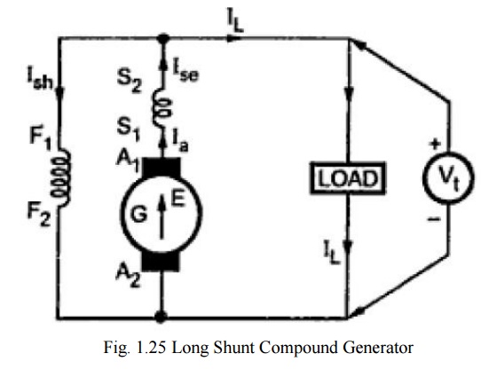
Series field current, Ise= Ia = IL+Ish
Shunt field current, Ish = V/Rsh
Terminal voltage, Vt = Eg - Ia(Ra+Rse)
Power developed in armature = EgIa
Power delivered to load = VtIL
2. Short shunt compound generator
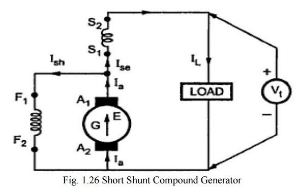
Series field current, Ise = IL
Shunt field current, Ish = V+IseRse/Rsh
Terminal voltage, Vt = Eg - IaRa+IseRse
Power developed in armature = EgIa
Power delivered to load = VtIL
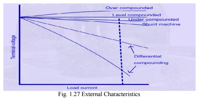
External Characteristics
Related Topics