Chapter: Software Architectures : Architectural Views
Architectural Structures And Views
ARCHITECTURAL
STRUCTURES AND VIEWS
So it is with software. Modern
systems are more than complex enough to make it difficult to grasp them all at
once. Instead, we restrict our attention at any one moment to one (or a small
number) of the software system's structures. To communicate meaningfully about
an architecture, we must make clear which structure or structures we are
discussing at the moment?which view we are taking of the architecture.
We will be using the related terms
structure and view when discussing architecture representation. A view is a
representation of a coherent set of architectural elements, as written by and
read by system stakeholders. It consists of a representation of a set of
elements and the relations among them. A structure is the set ofelements itself,
as they exist in software or hardware. For example, a module structure is the
set of the system's modules and their organization. A module view is the
representation of that structure, as documented by and used by some system
stakeholders. These terms are often used interchangeably, but we will adhere to
these definitions.
Architectural
structures can by and large be divided into three groups, depending on the
broad nature of the elements they show.
Ōłæ
Module structures. Here the elements are modules, which
are units of implementation. Modules represent a code-based way of considering
the system. They are assigned areas of functional responsibility. There is less
emphasis on how the resulting software manifests itself at runtime. Module
structures allow us to answer questions such as What is the primary functional
responsibility assigned to each module? What other software elements is a
module allowed to use? What other software does it actually use? What modules
are related to other modules by generalization or specialization (i.e.,
inheritance) relationships?
Ōłæ
Component-and-connector structures. Here the elements are
runtime components (which are the principal units of computation) and
connectors (which are the communication vehicles among components). Component-and-connector
structures help answer questions such as What are the major executing
components and how do they interact? What are the major shared data stores?
Which parts of the system are replicated? How does data progress through the
system? What parts of the system can run in parallel? How can the system's
structure change as it executes?
Ōłæ
Allocation structures. Allocation structures show the
relationship between the software elements and the elements in one or more
external environments in which the software is created and executed. They
answer questions such as What processor does each software element execute on?
In what files is each element stored during development, testing, and system
building? What is the assignment of software elements to development teams?
These
three structures correspond to the three broad types of decision that
architectural design involves:
Ōłæ
How is the system to be structured as a set of code units
(modules)?
Ōłæ
How is the system to be structured as a set of elements that
have runtime behavior (components) and interactions (connectors)?
Ōłæ
How is the system to relate to nonsoftware structures in
its environment (i.e., CPUs, file systems, networks, development teams, etc.)?
SOFTWARE
STRUCTURES
Some of
the most common and useful software structures are shown in Figure 2.3. These
are described in the following sections.
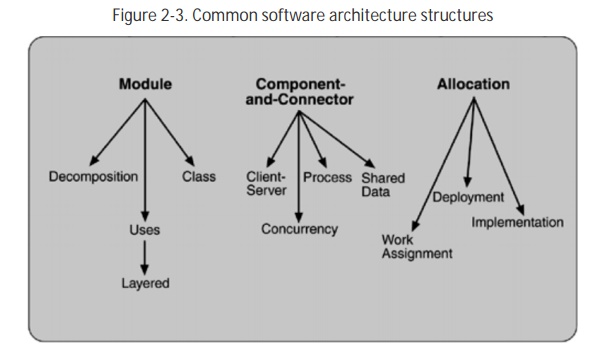
Module
Module-based structures include
the following.
Ōłæ
Decomposition.
The units are modules related to each other by the "is a submodule of
" relation, showing how larger modules are decomposed into smaller ones
recursively until they are small enough to be easily understood. Modules in
this structure represent a common starting point for design, as the architect
enumerates what the units of software will have to do and assigns each item to
a module for subsequent (more detailed) design and eventual implementation.
Modules often have associated products (i.e., interface specifications, code,
test plans, etc.). The decomposition structure provides a large part of the
system's modifiability, by ensuring that likely changes fall within the purview
of at most a few small modules. It is often used as the basis for the
development project's organization, including the structure of the
documentation, and its integration and test plans. The units in this structure
often have organization-specific names. Certain U.S. Department of Defense
standards, for instance, define Computer Software Configuration Items (CSCIs)
and Computer Software Components (CSCs), which are units of modular decomposition. In Chapter 15, we will see system function
groups and system functions as the units of decomposition.
Ōłæ
Uses.
The units of this important but overlooked structure are also modules, or (in
circumstances where a finer grain is warranted) procedures or resources on the
interfaces of modules. The units are related by the uses relation. One unit
uses another if the correctness of the first requires the presence of a correct
version (as opposed to a stub) of the second. The uses structure is used to
engineer systems that can be easily extended to add functionality or from which
useful functional subsets can be easily extracted.
Ōłæ
Layered.
When the uses relations in this structure are carefully controlled in a
particular way, a system of layers emerges, in which a layer is a coherent set
of related functionality. In a strictly layered structure, layer n may only use
the services of layer n ? 1. Many variations of this (and a lessening of this
structural restriction) occur in practice, however. Layers are often designed
as abstractions (virtual machines) that hide implementation specifics below
from the layers above, engendering portability. We will see layers in the case
studies of Chapters 3, 13 and 15.
Ōłæ
Class,
or generalization. The module units in this structure are called classes. The
relation is "inherits-from" or "is-an-instance-of." This
view supports reasoning about collections of similar behavior or capability
(i.e., the classes that other classes inherit from) and parameterized
differences which are captured by subclassing. The class structure allows us to
reason about re-use and the incremental addition of functionality.
Component-and-Connector
These structures include the
following.
Ōłæ
Process,
or communicating processes. Like all component-and-connector structures, this
one is orthogonal to the module-based structures and deals with the dynamic
aspects of a running system. The units here are processes or threads that are
connected with each other by communication, synchronization, and/or exclusion
operations. The relation in this (and in all component-and-connector
structures) isattachment, showing how the components and connectors are hooked
together. The process structure is important in helping to engineer a system's
execution performance and availability.
Ōłæ
Concurrency.
This component-and-connector structure allows the architect to determine
opportunities for parallelism and the locations where resource contention may
occur. The units are components and the connectors are "logical
threads." A logical thread is a sequence of computation that can be
allocated to a separate physical thread later in the design process. The
concurrency structure is used early in design to identify the requirements for
managing the issues associated with concurrent execution.
Ōłæ
Shared
data, or repository. This structure comprises components and connectors that
create, store, and access persistent data. If the system is in fact structured
around one or more shared data repositories, this structure is a good one to illuminate. It shows how data is produced and consumed by
runtime software elements, and it can be used to ensure good performance and
data integrity.
Ōłæ
Client-server.
If the system is built as a group of cooperating clients and servers, this is a
good component-and-connector structure to illuminate. The components are the
clients and servers, and the connectors are protocols and messages they share
to carry out the system's work. This is useful for separation of concerns
(supporting modifiability), for physical distribution, and for load balancing
(supporting runtime performance).
Allocation
Allocation structures include the
following.
Ōłæ
Deployment.
The deployment structure shows how software is assigned to hardware-processing
and communication elements. The elements are software (usually a process from a
component-and-connector view), hardware entities (processors), and
communication pathways. Relations are "allocated-to," showing on
which physical units the software elements reside, and "migrates-to,"
if the allocation is dynamic. This view allows an engineer to reason about
performance, data integrity, availability, and security. It is of particular
interest in distributed or parallel systems.
Ōłæ
Implementation.
This structure shows how software elements (usually modules) are mapped to the
file structure(s) in the system's development, integration, or configuration
control environments. This is critical for the management of development
activities and build processes.
Ōłæ
Work
assignment. This structure assigns responsibility for implementing and
integrating the modules to the appropriate development teams. Having a work
assignment structure as part of the architecture makes it clear that the
decision about who does the work has architectural as well as management
implications. The architect will know the expertise required on each team.
Also, on large multi-sourced distributed development projects, the work
assignment structure is the means for calling out units of functional
commonality and assigning them to a single team, rather than having them
implemented by everyone who needs them.
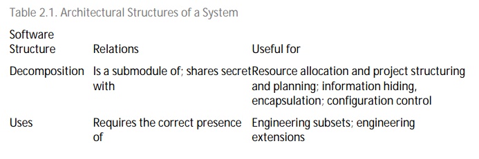
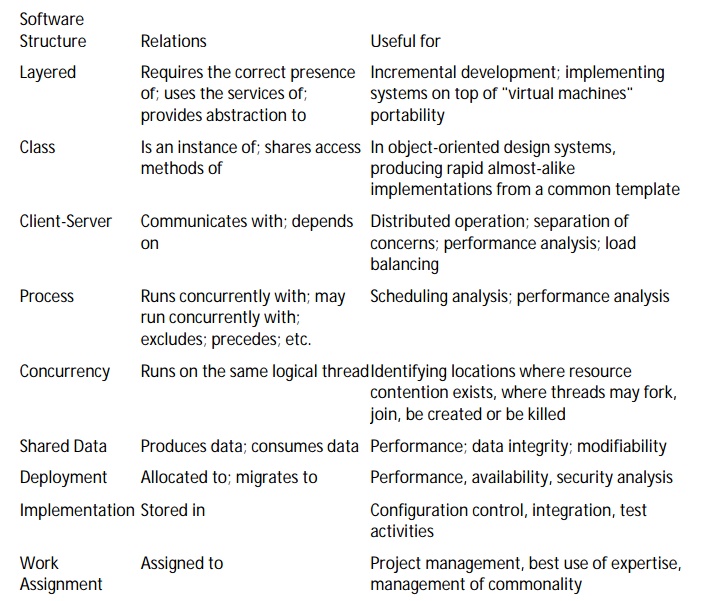
Table 2.1 summarizes the software
structures. The table lists the meaning of the elements and relations in each
structure and tells what each structure might be used for.
Although we often think about a
system's structure in terms of its functionality, there are system properties
in addition to functionality, such as physical distribution, process
communication, and synchronization, that must be considered at an architectural
level. Each structure provides a method for reasoning about some of the
relevant quality attributes. The uses structure, for instance, must be engineered
(not merely recorded) to build a system that can be easily extended or
contracted. The process structure is engineered to eliminate deadlock and
reduce bottlenecks. The module decomposition structure is engineered to produce
modifiable systems, and so forth. Each structure provides the architect with a
different view into the system and a different leverage point for design.
RELATING STRUCTURES TO EACH OTHER
Each of these structures provides
a different perspective and design handle on a system, and each is valid and
useful in its own right. Although the structures give different system
perspectives, they are not independent. Elements of one will be related to
elements of others, and we need to reason about these relations. For example, a
module in a decomposition structure may be manifested as one, as part of one,
or as several
components in one of the
component-and-connector structures, reflecting its runtime alter ego. In
general, mappings between structures are many to many.
Individual projects sometimes
consider one structure dominant and cast other structures, when possible, in
terms of it. Often, but not always, the dominant structure is module
decomposition. This is for a good reason: It tends to spawn the project
structure. Scenarios, described in Chapter 4, are useful for exercising a given
structure as well as its connections to other structures. For example, a
software engineer wanting to make a change to the client-server structure of a
system would need to consider the process and deployment views because
client-server mechanisms typically involve processes and threads, and physical
distribution might involve different control mechanisms than would be used if
the processes were colocated on a single machine. If control mechanisms need to
be changed, the module decomposition or layered view would need to be
considered to determine the extent of the changes.
Not all systems warrant
consideration of many architectural structures. The larger the system, the more
dramatic the differences between these structures tend to be; however, for
small systems we can often get by with less. Instead of working with each of
several component-and-connector structures, a single one will do. If there is
only one process, then the process structure collapses to a single node and
need not be carried through the design. If there is to be no distribution (that
is, if there is just one processor), then the deployment structure is trivial
and need not be considered further.
Structures represent the primary
engineering leverage points of an architecture. Individual structures bring
with them the power to manipulate one or more quality attributes. They
represent a powerful separation-of-concerns approach for creating the
architecture (and, later, for analyzing it and explaining it to stakeholders).
And, as we will see in Chapter 9, the structures that the architect has chosen
as engineering leverage points are also the primary candidates for the basis
for architecture documentation.
WHICH STRUCTURES TO CHOOSE?
We have briefly described a number
of useful architectural structures, and there are many more. Which ones should
an architect work on? Which ones should the architect document? Surely not all
of them.
There is no shortage of advice. In
1995, Philippe Kruchten [Kruchten 95] published a very influential paper in
which he described the concept of architecture comprising separate structures
and advised concentrating on four. To validate that the structures were not in
conflict with each other and together did in fact describe a system meeting its
requirements, Kruchten advised using key use cases as a check. This so-called
"Four Plus One" approach became popular and has now been
institutionalized as the conceptual basis of the Rational Unified Process.
Kruchten's four views follow:
Ōłæ
Logical.
The elements are "key abstractions," which are manifested in the
object-oriented world as objects or object classes. This is a module view.
Ōłæ
Process.
This view addresses concurrency and distribution of functionality. It is a component-and-connector
view.
Ōłæ
Development. This view shows the organization
of software modules, libraries, subsystems, and units of development. It is an
allocation view, mapping software to the development environment.
Ōłæ
Physical.
This view maps other elements onto processing and communication nodes and is
also an allocation view (which others call the deployment view).
At essentially the same time that
Kruchten published his work, Soni, Nord, and Hofmeister [Soni 95] published an
influential paper in which they reported the structures put into use across
many projects by the software architects in their organization. Their views
were conceptual, module interconnection, execution, and code. Once again, these
map clearly to the module, component-and-connector, and allocation models.
Other authors followed, and the
list of available structures grows ever more rich. Of course, you should not
use them all even though most of them will in fact exist in the system you are
building. Instead, consider that one of the obligations of the architect is to
understand how the various structures lead to quality attributes, and then
choose the ones that will best deliver those attributes. This point will be
treated at greater length in Chapter 9, on architectural representation.
ARCHITECTURAL
VIEW TYPES
Module Viewtype styles
ŌĆó
Decomposition
style
ŌĆó
Uses style
ŌĆó
Generalization
style
ŌĆó
Layered
style
Component and connector Viewtype
ŌĆó
Express
runtime behavior
ŌĆó
Described
in terms of connectors and components
ŌĆó
Objects,
processes, collection of objects are components
ŌĆó
Pipes,
repositories, sockets are connectors
ŌĆó
Middleware
is a connector Allocation Viewtype
ŌĆó
Maps
software units to elements of the environment(hardware, development team..)
ŌĆó
Deployment
style
ŌĆó
Implementation
style
Related Topics