Chapter: Communication Theory : Amplitude Modulation
AM Transmitters
AM TRANSMITTERS:
Transmitters
that transmit AM signals are known as AM transmitters. These transmitters are
used in medium wave (MW) and short wave (SW) frequency bands for AM broadcast.
The MW band has frequencies between 550 KHz and 1650 KHz, and the SW band has
frequencies ranging from 3 MHz to 30 MHz. The two types of AM transmitters that
are used based on their transmitting powers are:
·
High Level
·
Low Level
High
level transmitters use high level modulation, and low level transmitters use
low level modulation. The choice between the two modulation schemes depends on
the transmitting power of the AM transmitter. In broadcast transmitters, where
the transmitting power may be of the order of kilowatts, high level modulation
is employed. In low power transmitters, where only a few watts of transmitting
power are required , low level modulation is used.
High-Level
and Low-Level Transmitters Below figure's show the block diagram of high-level
and low-level transmitters. The basic difference between the two transmitters
is the power amplification of the carrier and modulating signals
Figure
(a) shows the block diagram of high-level AM transmitter.
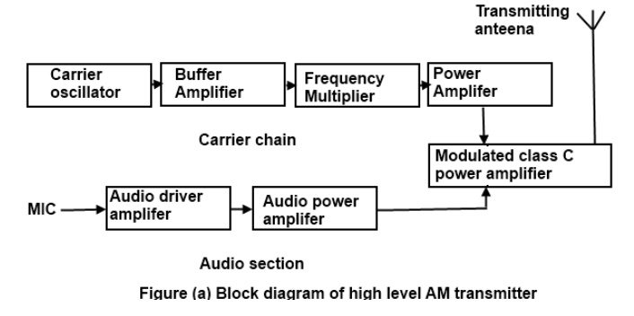
Figure
(a) is drawn for audio transmission. In high-level transmission, the powers of
the carrier and modulating signals are amplified before applying them to the
modulator stage, as shown in figure (a). In low-level modulation, the powers of
the two input signals of the modulator stage are not amplified. The required
transmitting power is obtained from the last stage of the transmitter, the
class C power amplifier.
The
various sections of the figure (a) are:
·
Carrier oscillator
·
Buffer amplifier
·
Frequency multiplier
·
Power amplifier
·
Audio chain
·
Modulated class C power amplifier
ü Carrier oscillator
The carrier
oscillator generates the carrier signal, which lies in the RF range. The
frequency of the carrier is always very high. Because it is very difficult to
generate high frequencies with good frequency stability, the carrier oscillator
generates a sub multiple with the required carrier frequency. This sub multiple
frequency is multiplied by the frequency multiplier stage to get the required
carrier frequency. Further, a crystal oscillator can be used in this stage to
generate a low frequency carrier with the best frequency stability. The
frequency multiplier stage then increases the frequency of the carrier to its
requirements.
ü Buffer Amplifier
The
purpose of the buffer amplifier is twofold. It first matches the output
impedance of the carrier oscillator with the input impedance of the frequency
multiplier, the next stage of the carrier oscillator. It then isolates the
carrier oscillator and frequency multiplier.
This is
required so that the multiplier does not draw a large current from the carrier
oscillator. If this occurs, the frequency of the carrier oscillator will not
remain stable.
ü Frequency Multiplier
The
sub-multiple frequency of the carrier signal, generated by the carrier
oscillator , is now applied to the frequency multiplier through the buffer
amplifier. This stage is also known as harmonic generator. The frequency
multiplier generates higher harmonics of carrier oscillator frequency. The
frequency multiplier is a tuned circuit that can be tuned to the requisite
carrier frequency that is to be transmitted.
ü Power Amplifier
The power
of the carrier signal is then amplified in the power amplifier stage. This is
the basic requirement of a high-level transmitter. A class C power amplifier
gives high power current pulses of the carrier signal at its output.
ü Audio Chain
The audio
signal to be transmitted is obtained from the microphone, as shown in figure
(a). The audio driver amplifier amplifies the voltage of this signal. This
amplification is necessary to drive the audio power amplifier. Next, a class A
or a class B power amplifier amplifies the power of the audio signal.
ü Modulated Class C Amplifier
This is
the output stage of the transmitter. The modulating audio signal and the
carrier signal, after power amplification, are applied to this modulating
stage. The modulation takes place at this stage. The class C amplifier also
amplifies the power of the AM signal to the reacquired transmitting power. This
signal is finally passed to the antenna., which radiates the signal into space
of transmission.
Figure
(b) shows the block diagram of a low-level AM transmitter.
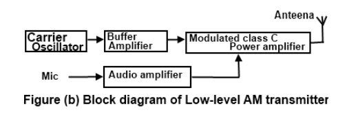
The
low-level AM transmitter shown in the figure (b) is similar to a high-level
transmitter, except that the powers of the carrier and audio signals are not
amplified. These two signals are directly applied to the modulated class C
power amplifier.
Modulation
takes place at the stage, and the power of the modulated signal is amplified to
the required transmitting power level. The transmitting antenna then transmits
the signal.
ü Coupling of Output Stage and Antenna
The
output stage of the modulated class C power amplifier feeds the signal to the
transmitting antenna. To transfer maximum power from the output stage to the
antenna it is necessary that the impedance of the two sections match. For this
, a matching network is required. The matching between the two should be
perfect at all transmitting frequencies. As the matching is required at
different frequencies, inductors and capacitors offering different impedance at
different frequencies are used in the matching networks.
The
matching network must be constructed using these passive components. This is
shown in figure ©
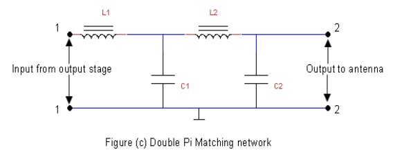
The
matching network used for coupling the output stage of the transmitter and the
antenna is called double π-network.
This network is shown in figure (c). It consists of two inductors , L1
and L2 and two capacitors, C1 and C2. The
values of these components are chosen such that the input impedance of the
network between 1 and 1'. Shown in figure (c) is matched with the output
impedance of the output stage of the transmitter. Further, the output impedance
of the network is matched with the impedance of the antenna.
The
double π matching network also filters
unwanted frequency components appearing at the output of the last stage of the
transmitter. The output of the modulated class C power amplifier may contain
higher harmonics, such as second and third harmonics, that are highly
undesirable. The frequency response of the matching network is set such that
these unwanted higher harmonics are totally suppressed, and only the desired
signal is coupled to the antenna.
ü Comparision of Am and Fm Signals
Both AM
and FM system are used in commercial and non-commercial applications. Such as
radio broadcasting and television transmission. Each system has its own merits
and demerits. In a Particular application, an AM system can be more suitable
than an FM system. Thus the two are equally important from the application
point of view.
ü Advantage of FM systems over AM Systems
The
advantages of FM over AM systems are:
The
amplitude of an FM wave remains constant. This provides the system designers an
opportunity to remove the noise from the received signal. This is done in FM
receivers by employing an amplitude limiter circuit so that the noise above the
limiting amplitude is suppressed. Thus, the FM system is considered a noise
immune system. This is not possible in AM systems because the baseband signal
is carried by the amplitude variations it self and the envelope of the AM
signal cannot be altered.
·
Most of the power in an FM signal is carried by the
side bands. For higher values of the modulation index, mc, the major portion of
the total power is contained is side bands, and the carrier signal contains
less power. In contrast, in an AM system, only one third of the total power is
carried by the side bands and two thirds of the total power is lost in the form
of carrier power.
·
In FM systems, the power of the transmitted signal
depends on the amplitude of the unmodulated carrier signal, and hence it is
constant. In contrast, in AM systems, the power depends on the modulation index
ma. The maximum allowable power in AM systems is 100 percent when ma is unity.
Such restriction is not applicable int case of FM systems. This is because the
total power in an FM system is independent of the modulation index, mf and
frequency deviation fd. Therefore, the power usage is optimum in an FM system.
·
In an AM system, the only method of reducing noise
is to increase the transmitted power of the signal. This operation increases
the cost of the AM system. In an FM system, you can increase the frequency
deviation in the carrier signal to reduce the noise. if the frequency deviation
is high, then the corresponding variation in amplitude of the baseband signal
can be easily retrieved. if the frequency deviation is small, noise 'can
overshadow this variation and the frequency deviation cannot be translated into
its corresponding amplitude variation. Thus, by increasing frequency deviations
in the FM signal, the noise effect can he reduced. There is no provision in AM
system to reduce the noise effect by any method, other than increasing itss
transmitted power.
·
In an FM signal, the adjacent FM channels are
separated by guard bands. In an FM system there is no signal transmission
through the spectrum space or the guard band. Therefore, there is hardly any
interference of adjacent FM channels. However, in an AM system, there is no
guard band provided between the two adjacent channels. Therefore, there is
always interference of AM radio stations unless the received signalis strong
enough to suppress the signal of the adjacent channel.
ü The disadvantages of FM systems over AM
systems
· There are an infinite number of side bands in an FM signal and therefore the theoretical bandwidth of an FM system is infinite. The bandwidth of an FM system is limited by Carson's rule, but is still much higher, especially in WBFM. In AM systems, the bandwidth is only twice the modulation frequency, which is much less than that of WBFN. This makes FM systems costlier than AM systems.
· The equipment of FM system is
more complex than AM systems because of the complex circuitry of FM systems;
this is another reason that FM systems are costlier AM systems.
· The receiving area of an FM system is smaller than an AM system consequently FM channels are restricted to metropolitan areas while AM radio stations can be received anywhere in the world. An FM system transmits signals through line of sight propagation, in which the distance between the transmitting and receiving antenna should not be much. in an AM system signals of short wave band stations are transmitted through atmospheric layers that reflect the radio waves over a wider area.
Related Topics