Chapter: Civil : Design of Reinforced Concrete Elements : Methods Of Design Of Concrete Structures
Working Stress Method Design
WORKING STRESS METHOD DESIGN
GENERAL
PRINCIPLES OF WORKING STRESS DESIGN
(a)
General features
During the early part of 20th century,
elastic theory of reinforced concrete sections outlined was developed which
formed the basis of the working stress or permissible stress method of design
of reinforced concrete members. In this method, the working or permissible
stress in concrete and steel are obtained applying appropriate partial safety
factors to the characteristics strength of the materials. The permissible
stresses in concrete and steel are well within the linear elastic range of the
materials.
The design based on the working stress method
although ensures safety of the structures at working or services loads, it does
not provide a realistic estimate of the ultimate or collapse load of the
structure in contrast to the limit state method of design. The working stress
method of design results in comparatively larger and conservative sections of
the structural elements with higher quantities of steel reinforcement which
results in conservative and costly design. Structural engineers have used this
method extensively during the 20th
century and presently the method is incorporated as an alternative to the limit
state method in Annexure -B of the recently revised Indian Standard Code Is :
456 -2000 for specific applications.
The permissible stresses in concrete under service
loads for the various stress states of compressive, flexure and bond is
compiled in Table 2.1 (Table 21 of IS ; 456 -2000)
The
permissible stress in different types of steel reinforcement is shown in table
2.2 (Table 22 of IS 456
-2000)
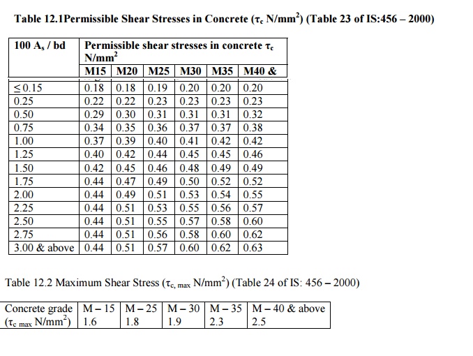
The permissible shear stress for various grades of
concrete in beams is shown in Table 12.1 (Table 23 of IS: 456 -2000)
The maximum shear stress permissible in concrete for
different grades is shown in Table 12.2 Table 12.2 (Table 24 of IS: 456 -2000)
In
the case of reinforced concrete slabs, the permissible shear stress in concrete
is obtained by multiplying the values given in Table 2.1 by as shown in Table
12.3 (Section 40.2.1.1. of IS; 456 -2000)
Note: As
is that area of longitudinal tension reinforcement which continues at least
one effective depth beyond the section being considered except at
supports where the full area of tension reinforcement may be used provided the
detailing conforms to 26.2.3.
The maximum shear stress permissible in concrete for
different grades is shown in Table 12.2 (Table 24 of IS 456 -2000)
In the case of reinforced concrete slabs, the
permissible shear stress in concrete is obtained by multiplying the3 values in
Table 2.1 by a fac shown in Table 12.3 (Section 40.2.1.1. of IS 456 -2000)
(b) General
design procedure
In the working stress design, the cross -sectional
dimensions are assumed based on the basic span / depth ratios outlined in
Chapter 5 (Table 5.1 and 5.2) (Section 23.2.1. of IS: 456 -2000)
The working load moments and shear forces are
evaluated at critical sections and the required effective depth is checked by
using the relation:
d = ?
M / Q.b
Where d = effective depth of section M =
working load moment b = width of section
Q = a constant depending upon the
working stresses in concrete and steel, neutral axis depth factor (k) and lever
arm coefficient (f).
For different grades of concretepiledin
Tableand2.3. steelThedepth th provided should be equal to or greater than the
depth computed by the relation and the area of reinforcement required in the
section to resi
The number of steel
bars required is selected with due regard to the spacing of bars and cover
requirements.
After complying with
flexure, the section is generally checked for resistance against shear forces
by calculating thec givennominal=(Vby/bd)shear? stress ?
Where V = Working shear force at critical section.
The permissible shearc)depends
uponstressthepercentagereinforcementsconcreteinthecross -(? section and grade
of concrete as shown in Table 12.1
Ifc< ?vsuitable? shear
reinforcements are designed in beams at a spacing sv given by the
relation;
Sv
= [ 0.87 fy Asv d / Vus]
Where sv = spacing of stirrups
Asv
= cross -sectional area of stirrups legs
fy
= Characteristics strength of stirrup reinforcement
d
= effective depth
Vs
= [ V -?c.b .d]
Ifv< ?c,
nominal? shear reinforcements are provided in beams are provided in beams at a
spacing given by
Sv
[ 0.87 fy Ast /
0.4 b]
In case of slabs, the
permissible shear stres Also in the case of slabsv)shouldnot
excetheed nominalhalfthecmaxsheshownvalueinrs
Table 12.2. In such cases the thickness of the slab
is increased and the slab is redesigned.
In the case of compression
members, the axial load permissible on a short column reinforced with
longitudinal bars and lateral ties is given by
P =cc A(?c+sc
?Asc)
Where scc = permissible stress in
concrete in direct compression (Refer Table 2.1)
Ac
= cross -sectional area of concrete excluding the area of reinforcements.
Ssc
= permissible compressive stress in reinforcement
Asc = cross -sectional area
of longitudinal steel bars.
Related Topics