Chapter: Electrical Drives & Control : Drive Motor Characteristics
Three Phase Induction Motor: Construction, Working Principle
THREE PHASE INDUCTION MOTOR
Types :
There are two types of 3-phase induction motor based on the type of rotor used:
Squirrel cage induction motor.
Slip ring induction motor.
Slip-ring induction motor over squirrel cage Induction motor
Advantages:
It is possible to speed control by regulating rotor resistance.
High starting torque of 200 to 250% of full load voltage.
Low starting current of the order of 250 to 300% of the full load current.
Hence slip ring induction motors are used where one or more of the above requirements are to be met.
1. CONSTRUCTIONAL DETAILS
Conversion of electrical power into mechanical power takes place in the rotating part of an electric motor. In A.C. motors, rotor receives electric power by induction in exactly the same way as the secondary of a two-winding transformer receives its power from the primary. Hence such motors are known as a rotating transformer i.e. one in which primary winding is stationary but the secondary is free to rotate.
An induction motor essentially consists of two main parts:
stator and
Rotor.
Stator:
The stator of an induction motor is in principle, the same as that of a synchronous motor (or) generator.
It is made up of a number of stampings, which are slotted to receive the windings.
The stator carries a 3-phase winding and is fed from a 3-phase supply.
It is wound for a definite number of poles, the exact number of poles being determined by the requirements of speed.
The number of poles are higher, lesser the speed and vice-versa.
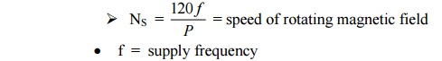
The stator winding, when supplied with a 3-phase currents, produce a magnetic flux, which is of constant magnitude but which revolves at synchronous speed (Ns = 120 x f / p).
This revolving magnetic flux induces emf in rotor by mutual induction.
Rotor:
Squirrel cage Rotor:
Motors employing this type of rotor are known as squirrel cage induction motor.
(ii). Phase wound (or) slip-ring Rotor:
Motors employing this type of rotor are widely known as “phase-wound” motors or wound motor or “slip-ring” motors.
SQUIRREL CAGE ROTOR:
Almost 90 percentage of induction motors are squirrel-cage type, because this type of rotor has the simplest and most rugged construction imaginable and is almost indestructible.
The Rotor consists of cylindrical laminated core with parallel slots for carrying the rotor conductors which, it should be noted clearly, are not wires but consists of heavy bars of copper, aluminium or alloys.
One bar is placed in each slot; rather the bars are inserted from the end when semi-enclosed slots are used.
The rotor bars are brazed or electrically welded or bolted to two heavy and stout short circuiting end-rings, thus giving us, what is called a squirrel cage construction.
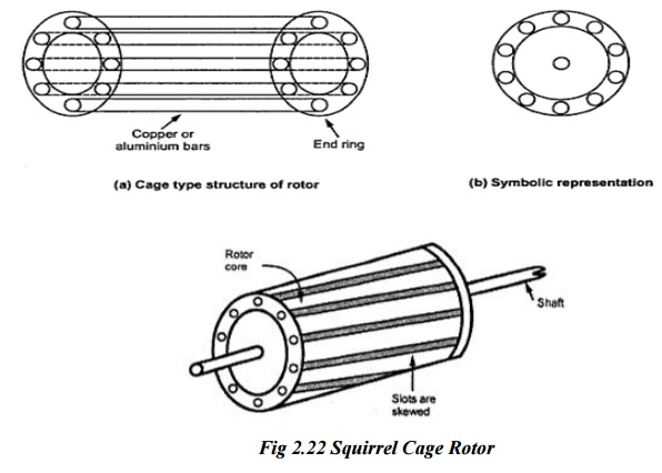
The Rotor bars are permanently short-circuited on themselves; hence it is not possible to add any external Resistance in series with the Rotor circuit for starting purposes.
The rotor slots are not quite parallel to the shaft but are purposely given a slight skew. This is useful in two ways.
It helps to make the motor run quietly by reducing the magnetic hum and
It helps in reducing the locking tendency of the rotor. i.e. the tendency of the rotor teeth to remain under the stator teeth due to direct magnetic attraction between the two.
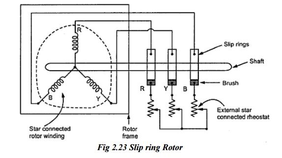
PHASE-WOUND ROTOR:
This type of rotor is provided with 3-phase, double-layer, distributed winding consisting of coils are used in alternators.
The Rotor is wound for as many poles as the number of stator poles and is always wound 3-phase even when the stator is wound for two-phase.
The three phases are shorted internally.
The other three winding terminals are slip-rings mounted on the shaft with brushes resting on them.
These three brushes are further externally connected to a 3-phase star connected Rheostat.
This makes possible the introduction of additional resistance in the rotor circuit during the starting period for increasing the starting torque of the motor.
When running under normal conditions, slip-rings are automatically short circuited by means of a metal collar, which is pushed along the shaft and connects all the rings together.
Frame:
Made of close-grained alloy cast iron.
Stator and Rotor core:
Built from high quality low loss silicon steel laminations and flash enameled on both sides.
Stator and Rotor windings:
Have moisture proof tropical insulation and embodying mica and high quality varnishes.
Are carefully spaced for most effective air circulation and are rigidly braced to withstand centrifugal forces and any short circuit stresses.
Air gap:
The stator rabbets and bore are machined carefully to ensure uniformity of air gap.
Shaft and Bearings:
Ball and roller bearings are used to suit heavy duty, trouble free running and for enhanced service life.
Fans:
Light aluminium fans are used for adequate circulation of cooling air and are securely keyed onto the Rotor shaft.
Slip-Rings and Slip-Ring Enclosures:
Slip rings are made of high quality phosphor bronze and are of molded construction.
2. WORKING PRINCIPLE OF THREE PHASE INDUCTION MOTOR
Working principle:
Induction motor works on the principle of electromagnetic induction.
When three phase supply is given to the stator winding, a rotating magnetic field of constant magnetic field is produced.
The speed of rotating magnetic field is synchronous speed, NS r.p.m.
This rotating field produces an effect of rotating poles around a rotor. Let direction of this magnetic field is clockwise as shown.
Now at this instant rotor is stationary and stator flux R.M.F. is rotating. So its obvious that there exists a relative motion between the R.M.F. and rotor conductors.
Now the R.M.F. gets cut by rotor conductors as R.M.F. sweeps over rotor conductors.
Whenever a conductor cuts the flux, emf. gets induced in it. So e.m.f.gets induced in the rotor conductors called rotor induced emf. this is electro – magnetic induction.
As rotor forms closed circuit, induced emf. circulates current through rotor called rotor current.
Any current carrying conductor produces its own flux. So rotor produces its flux called rotor flux. For assumed direction of rotor current, the direction of rotor flux is clockwise as shown.
This direction can be easily determined using right hand thumb rule.
Now there are two fluxes, one R.M.F. and another rotor flux.
Both the fluxes interact with each. On left of rotor conductor, two fluxes are in same direction hence added up to get high flux area.
On right side of rotor conductor, two fluxes are in opposite direction hence they cancel each other to produce low flux area.
So rotor conductor experiences a force from left to right, due to interaction of the two fluxes.
As all rotor conductor experiences a force, overall rotor experiences a torque and starts rotating.
So interaction of the two fluxes is very essential for a motoring action. As seen from the figure, the direction of force is same as that of rotating magnetic field. Hence rotor starts rotating in the same direction as that of R.M.F.
Related Topics