Chapter: Civil : Structural Analysis : Finite Element Method
Structural Analysis: Finite Element Method
FINITE ELEMENT METHOD
1 INTRODUCTION
There are two version of FEM:
1. Flexibility Method or Force Method
2. Stiffness Method or Displacement Method.
� The set
of equations in the stiffness method are the equilibrium equations relating
displacements of points.
� Rayleigh-
Ritzisan approximate method based on energy principle by
Which we
can obtain equilibrium equations in matrix form.
1 IMPORTANT DEFINITION
Nodes are points on the structure at
which displacements and rotations are to be found or prescribed.
Element is a
small domain on which we can solve the boundary value problem in terms
of the displacements and forces of the nodes on the element.
The discrete representation of the structure geometry by
elements and nodes is called a mesh.
The process of creating a mesh (discrete entities) is called discretization.
Inter polation function isakinematicallyadmissible
displacement function defined on an element that can be used for interpolating
displacement values between the nodes.
The mesh, boundary conditions, loads,
and material properties representing the actual structure is called a model.
Element stiffness matrix relate
the displacements to the forcesat the element nodes.
Global stiffness matrix is an assembly
of element stiffness matrix that relates the displacements of the nodes on
the mesh to applied external forces.
1.2.Stepsin FEM procedure
1.Obtain element
stiffness and element load vector.
2.Transform
from local orientation to global orientation.
3.Assemble
the global stiffness matrix and load vector.
4.Incorporate
the external loads
5.Incorporate
the boundary conditions.
6.Solve the
algebraic equations for nodal displacements.
7.Obtain reaction force, stress, internal forces, strain
energy.
8.Interpret
and check the results.
9.Refinemeshif
necessary, and repeat the above steps.
2.DISCRETISATION OF STRUCTURE
Discretization is the process of separating the
length, area or volume we want to analyze into discrete (or separate) parts or
elements.
3.DISPLACEMENT FUNCTIONS
The continuum is separated by imaginary lines or
surfaces into a number of finite element
�
The elements are assumed to be connected at
discrete number of nodal points situated on their boundaries.
�
Generalized displacements are the basic unknowns.
�
A function uniquely defines displacement field in
terms of nodal displacements.
�
Compatibility between elements.
�
2D - 3D
elasticity problems, displacement compatibility.
�
Plates and shells, displacements and their partial
derivatives.
�
All possible rigid body displacements included (if
not will not converge).
� All
uniform strain states included. The displacement function, uniquely defines
strain
within an element in terms of nodal displacements.
These
strains with any initial strain, together with elastic properties define the stress
state.
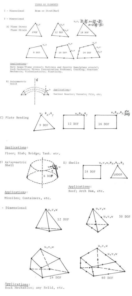
4 TYPES OF ELEMENT
Three are three types of elements are available.
�
1D Elements
�
2D Elements
�
3D Elements
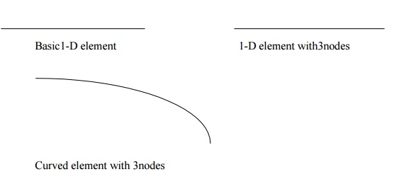
4.1 1D
Elements (Beam Element)
A beam can be approximated as a one dimensional
structure. It can be split into one dimensional beam elements. So also, a
continuous beam or a flexure frame can be discretized using 1D beam elements.
A pin
jointed truss is readily made up of discrete 1D ties which are duly assembled.
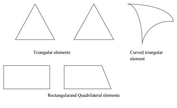
4.2 2 D
Elements (Triangular Element)
A plane wall ,plate, diaphragm, slab, shell etc.,
can be approximated as an assemblage of 2D elements. Triangular elements are
the most used ones. when our 2D domain has curved boundaries it may be
advantageous to choose elements that can have curved boundaries.
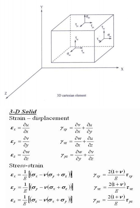
4.3 3 D
Elements (Truss Element)
Analysis of solid bodies call for the use of 3 D elements.
These have the drawback that the visualizations is complex. The size of the
stiffness matrix to be handled can become enormous and unwieldy.
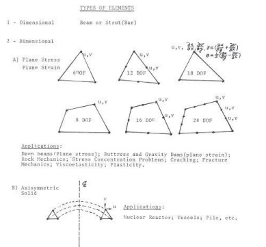
5 PLANE STRESS AND PLANE STRAIN
The plane stress problem is one in which two
dimensions ,length and breadth are comparable and thickness
dimension is very small (less than 1/10).Hence normal stress ?2 and shear
stresses ?xz,?yzare zero.
{?
}= [D]{e }
[D]=Stress strain relationship matrix (or)
constitutive matrix for plane stress problems. We have seen that in the Z
direction the dimension of the plate in the plane stress
problem
is very small. In plane strain problem, on the contrary the structure is
infinitely long in
the Z
direction. Moreover the boundary and body forces do not vary in the Z
directions.
{?
}= [D]{e }
[D]=Stress strain relationship matrix (or) constitutive matrix
for plane strain problems.
FINITE
ELEMENT METHOD
1. What is
meant by Finite element method?
Finite element method (FEM)is a numerical technique for solving
boundary value problems in which a large domain is divided into smaller pieces
or elements. The solution is determined by asuuming certain ploynomials. The small
pieces are called finite element and the polynomials are called shape functions.
2. List out
the advantages of FEM.
� Since the
properties of each element are evaluated separately differnt material
properties can be incorporated for each element.
� There is
no restriction in the shape of the medium.
� Any type of
boundary condition can be adopted.
3. List out
the disadvantages of FEM.
�The computational cost is high.
�The solution is approximate and several checks are required.
4. Mention
the various coordinates in FEM.
� Local or
element coordinates
� Natural
coodinates
� Simple natural
coodinates
� Area coordiantesor
Triangular coordiantes
� Generalised
coordinates
5. What are
the basic steps in FEM?
� Discretization
of the structure
� Selection
of suitable displacement fuction
� Finding the
element properties
� Assembling
the element properties
� Applying the
boundary conditions
� Solving the
system of equations
� Computing
additional results
6. What is
meant by discretization?
Discretization is the process of subdividing the given body into
a number of elements which results in a system of equivalent finite elements.
7. What are the factors governing the selection of
finite elements?
�The geometry of the body
�The number of independent space coordinates
�The nature of stress variation expected
8. Define
displacement function.
Displcement function is defined as simple functions which are assumed
to approximate the displacements for each element. They may assumed in the form
of poynomials, or trignometrical functions.
9. Briefly
explain a few terminology used in FEM.
The various
terms used in FEM are explained below.
�
Finite element-Small
elements used for subdividing the given domain tobe analysed are called finite elements. The seelements
may be 1D, 2D or 3D elements depend in on the type of structure.
�
Nodes and nodal points- The intersection
of the differnt sides of elements are called nodes. Nodes are of two types - external
nodes and internal nodes.
O External nodes - The nodal
point connecting adjacent elements.
O Internal nodes- The extra
nodes used to increase the accuracy of solution.
�
Nodal lines - The interface
between elements are called nodal lines.
�
Continuum- The domain
in which matter exists at every point is called a continuum. It can be assumed
as having infinite number of connected particles.
�
Primary unknowns- The main
unknowns involved in the formulation of the element properties are known as
primary unknowns.
�
Secondary unknowns- These unknowns
are derived from primary unknowns are known as secondary unknowns. In
displacement formulations, displacements are treated as primary unknowns and
stress, strain, moments and shear force are treated as secondary unknowns.
10.
What are differnt types of elements used in
FEM?
The various elements used in FEM are classified as:
� One dimensional
elements(1D elements)
� Two
dimensional elements(2D elements)
� Three dimensional
elements(3D elements)
11.
Whatare1-D elements? Give examples.
Elements having a minimum of two nodes are called 1D elements.
Beams are usually approximated with 1Delements. These may be straight or curved.
There can be additional nodes within the element.
12.
Whatare2-D elements? Give examples.
A plane wall, plate, diaphragm, slab, shell etc. can be
approximated as an assemblage of 2-D elements. Most commonly used elements are triangular,
rectangular and quadrilateral elements.
13.
What are 3-D elements? Give examples.
3-D elements are used for modeling solid bodies and the various
3-Delements are tetrahedron, hexa hedron, and curved rectangular solid.
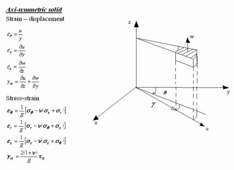
14.
What are axisymmetric elements?
Axisymmetric elements are obtained by rotatinga1-D line about
an axis. Axisymmetric elements are shown in the figure below.
15.
Define Shape function.
Shape function is also called an approximate function or an
interpolation function whose value is equal to unity at the node considered and
zeros at all other nodes. Shape function is represented by Ni where i =nodeno.
16.
What are the properties of shape functions?
The properties of shape functions are:
� Theno of shape
functions will be equal to theno of nodes present in the element.
�
Shape function will have a unit value at the node
considered and zero value at other nodes.
� The sum
of all the shape function is equal to 1. i. e. SNi =1
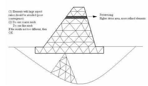
17.
Define aspect ratio.
Element aspect ratio is defined as the ratio of the largest
dimension of the element to its smallest dimension.
18.
What are possible locations for nodes?
The possible locations for nodes are:
�Point of application of concentrated load.
�Location where there is a change in intensity of loads
�Locations where there are discontinuities in the geometry of the
structure
�Interfaces between materials of different properties.
19.
What are the characteristics of displacement functions?
Displacement functions should have the following
characteristics:
The displacement field should be continuous.
� The displacement
function should be compatible between adjacent elements
� The displacement
field must represent constant strain states of elements
�
The displacement function must represent rigid
body displacements of an element.
20.
What is meant by plane strain condition?
Plane strain is a state of strain in which normal strain and
shear strain directed perpendicular to the plane of body is assumed to be zero.
Related Topics