Chapter: Civil : Strength of Materials : Advanced Topics In Bending of Beams
Strength of Materials- Advanced Topics In Bending of Beams
ADVANCED TOPICS IN BENDING OF BEAMS
1 UNSYMMETRICAL BENDING
The plane of loading
(or) that of bending does not lie in (or) a plane that contains the principle centroidal axis of the cross-
section; the bending is called Unsymmetrical bending.
2 STATE THE TWO REASONS
FOR UNSYMMETRICAL BENDING
(i) The section is symmetrical (viz. Rectangular,
circular, I section) but the load line
is inclined to both the principal axes.
(ii) The section is unsymmetrical (viz. Angle
section (or) channel section vertical
web) and the load line is along any centroidal axes.
3.SHEAR CENTRE
The shear centre (for any transverse section
of the beam) is the point of
intersection of the bending axis and the plane of the transverse
section. Shear centre is also known as
'centre of twist'
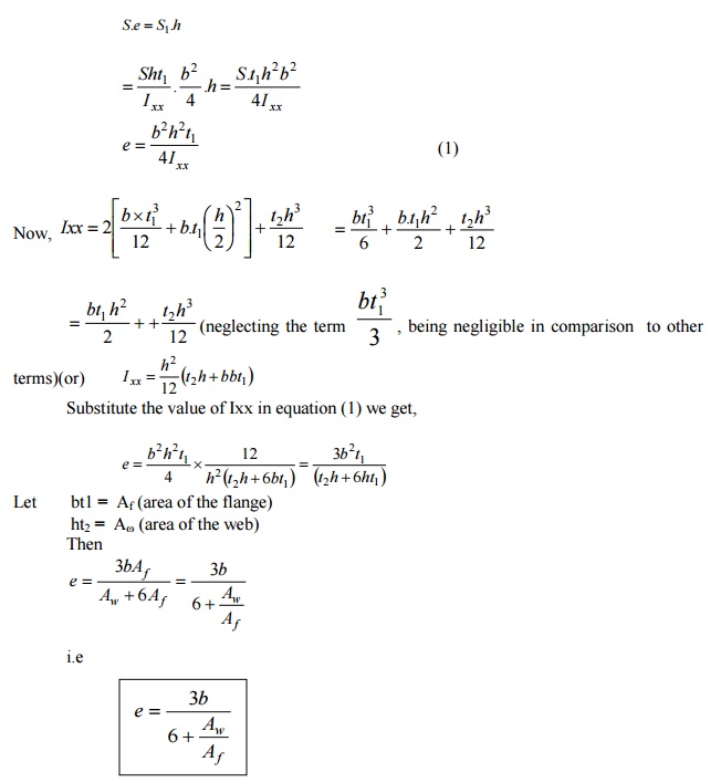
4.WRITE THE SHEAR CENTRE EQUATION FOR CHANNEL
SECTION

e = Distance of the shear centre (SC ) from the web along the symmetric axis XX
Aw
= Area of the web
Af
= Area of the flange
A
CHANNEL SECTION HAS FLANGES 12 CM X 2 CM AND WEB 16 CM X 1 CM. DETERMINE THE SHEAR CENTRE OF THE CHANNEL
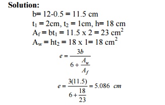
5 WRITE THE SHEAR CENTRE EQUATION FOR
UNSYMMETRICAL I SECTION
e = Distance of the shear centre (SC) from the
web along the symmetric axis XX t1
= thickness of the flange
h = height of
the web
b1
= width of the flange in right portion.
b2
= width of the flange in left portion.
Ixx
= M.O.I of the section about XX axis.
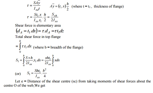
6 DERIVE THE EQUATION OF SHEAR CENTRE
FOR CHANNEL SECTION
A
channel
section (flanges: b x t1 ;
Web h x t2) with XX as the
horizontal symmetric axis.
Let S =
Applied shear force. (Vertical downward X)
(Then S is
the shear force in the web in the upward direction)
S1 = Shear force in the top flange
(there will be equal and opposite shear force
in the bottom flange as shown.)
Now, shear
stress (t) in the flange at a distance of x
from the right hand edge (of the top flange)
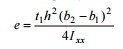
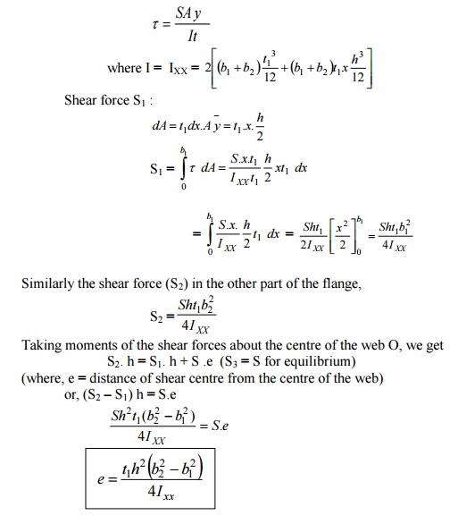
7 DERIVE THE EQUATION OF SHEAR CENTER
FOR UNEQUAL-SECTION Solution:
An unequal I -section which is symmetrical about XX axis.
Shear stress in any layer,
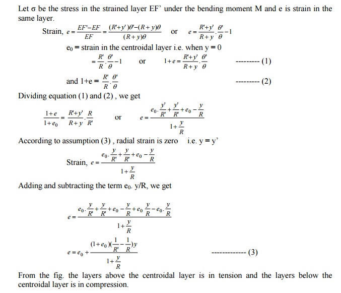
8 DERIVE THE STRESSES IN CURVED BARS US
ING WINKLER-BACH THEORY
The simple bending formula, however, is not
applicable for deeply curved beams where
the neutral and centroidal axes do not coincide. To deal with such cases
Winkler -Bach Theory is used.
A bar ABCD initially; in its unstrained state.
Let AB?CD? be
th bar.
Let R =
Radius of curvature of the centroidal axis HG.
Y = Distance of the fiber EF from the
centroidal layer HG.
R? = Radius
of curvature of
HG?
M = Uniform bending moment applied to the
beam (assumed positive when tending to
increase the curvature)
R? =
Original angle subtended by the centroidal axis HG at its centre of curvature O and
q? =
Angle subtended by
HG? (after ben q?
For finding
the strain and stress normal to the section, consider the fibre EF at a
distance y from the centroidal axis.
Let ? be the
stress in the strained layer EF same
layer.
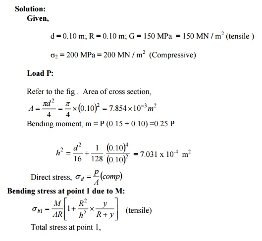
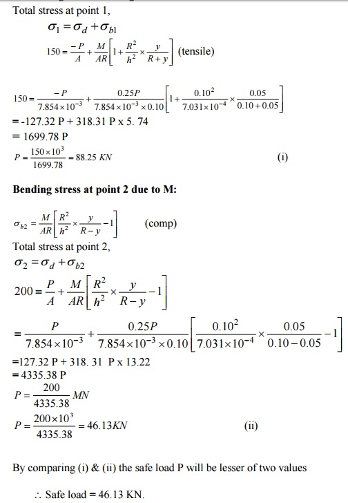
The curved member shown in fig. has a solid
circular cross -section 0.01 m in diameter.
If the maximum tensile and compressive stresses in the member are not to
exceed 150 MPa and 200 MPa. Determine
the value of load P that can safely be carried by the member.
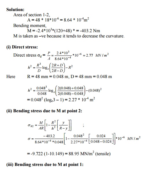
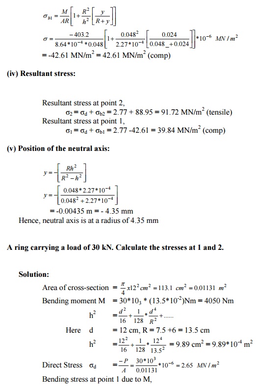
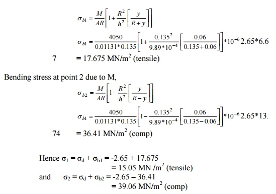
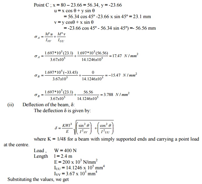
A frame subjected to a load of 2.4 kN. Find
(i) The resultant stresses at a point 1 and
2; (ii) Position of neutral
axis.
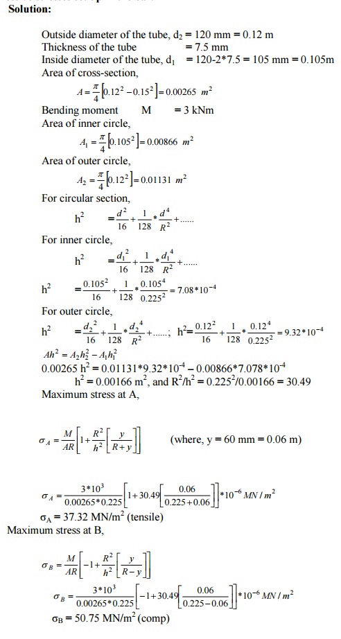
A curved bar is formed of a tube of 120 mm
outside diameter and 7.5 mm thickness. The
centre line of this is a circular arc of radius 225 mm. The bending
moment of 3 kNm tending to increase
curvature of the bar is applied. Calculate the maximum tensile and compressive stresses set up in the bar.
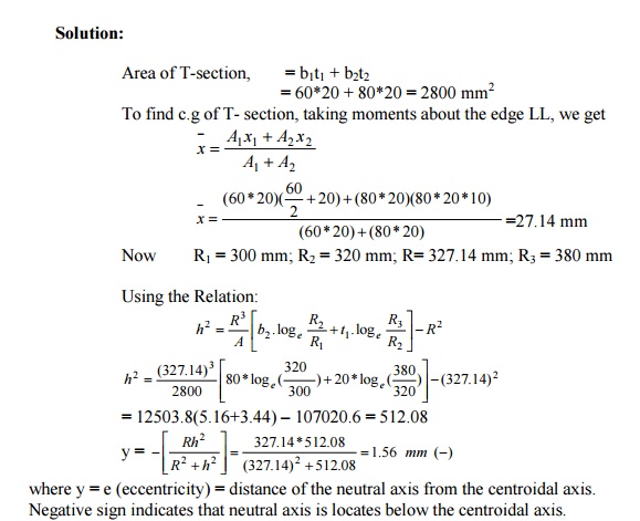
A CURVED BEAM HAS A
T-SECTION. THE INNER RADIUS IS 300 MM. WHAT IS
THE ECCENTRICITY OF THE SECTION?
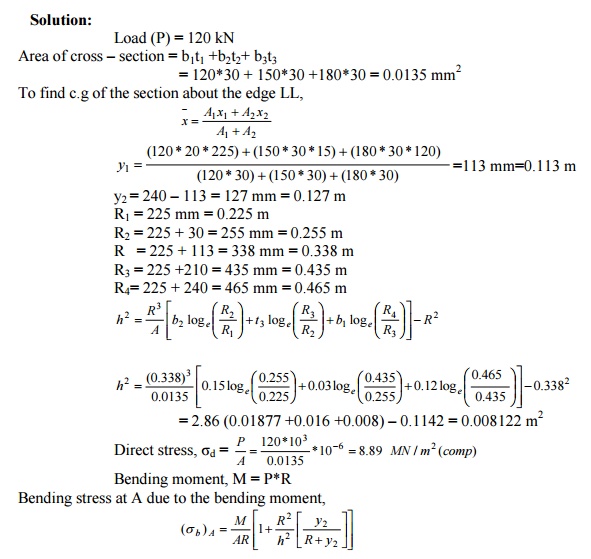
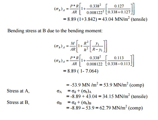
C- FRAME SUBJECTED TO A LOAD OF 120 KN.
DETERMINE THE STRESSES AT A AND B.
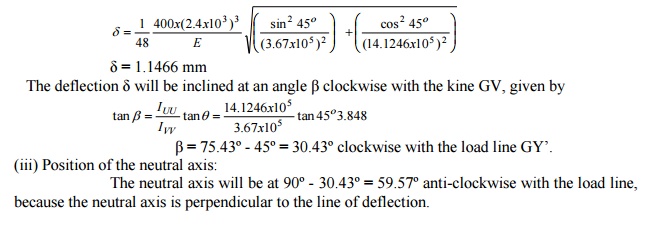
DERIVE THE FORMULA FOR THE DEFLECTION OF BEAMS
DUE TO
UNSYMMETRICAL BENDING
Solution:
Tthe
transverse section of the beam with centroid G. XX and YY are two rectangular co-ordinate axes
and UU and
VV are the
pri XY set of co-ordinates axes.
W is the load acting along the line YY on the section of the beam. The load W can be resolved into the following
two components:
(i)
W
sin ? ��
along UG
(ii)
W
cos ? ��
along VG
Let,u= Deflection?
caused by the
component W si
VV axis, and
v = Deflection
caused long by the thelineGV due component
to bendingabodt W co
UU axis.
Then depending
upon the end u
conditionsandvare?givenby
of th
where, K = A constant depending on the end
conditions of the beam and position of
the load along the beam, and
l = length of
the beam
The total
or resultant deflection
? can then
A 80 mm x 80 mm x 10 mm angle section shown in
fig. is used as a simply supported beam
over a span of 2.4 m. It carries a load of 400 kN along the line YG,
where G is the centroid of the section.
Calculate (i) Stresses at the points A, B and C of the mid -section of the beam (ii) Deflection of the beam at the mid-section
and its direction with the load line (iii)
Position of the neutral axis. Take E = 200 GN/m2
10
STATE THE PARALLEL AXES AND PRINCIPAL MOMENT OF INERTIA
If the two axes about which the product of
inertia is found, are such , that the
product of inertia becomes zero, the two axes are then called the
principle axes. The moment of inertia
about a principal axes is called the principal moment of inertia.
11 STRESS CONCENTRATION
The term stress gradient is used to indicate
the rate of increase of stress as a stress
raiser is approached. These localized stresses are called stress
concentration.
12 STRESS- CONCENTRATION FACTOR
It is defined as the ratio of the maximum
stress to the nominal stress.
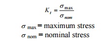
?max = maximum
stress
?nom = nominal
stress
13 FATIGUE STRESS CONCENTRATION FACTOR
The fatigue stress -concentration factor (Kf
) is defined as the ratio of flange limit
of unnotched specimen to the fatigue limit of notched specimen under
axial (or) bending loads.
K
f =1+q(Kt -1)
Value of q ranges from zero to one.
14 SHEAR FLOW
Shear flow is defined as the ratio of
horizontal shear force H over length of the
beam x. Shear flow is acting along the longitudinal surface located at
discharge y1.Shear flow is
defined by q.
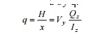
H
= horizontal shear force
15 EXPLAIN THE
POSITION OF SHEAR CENTRE IN VARIOUS SECTIONS
(i) In case of a beam having two axes of
symmetry, the shear centre coincides with the centroid.
(ii)
In case of sections having one axis of
symmetry, the shear centre does not
coincide with the centroid but lies on the axis of symmetry.
16 STATE THE
PRINCIPLES INVOLVED IN LOCATING THE SHEAR CENTRE
The principle involved in locating the shear
centre for a cross -section of a beam is that the loads acting on the beam must
lie in a plane which contains the resultant shear force on each cross-section of the beam as
computed from the shearing stresses.
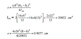
DETERMINE THE POSITION OF SHEAR CENTRE OF THE
SECTION OF THE BEAM
Solution:
t1
= 4 cm, b1 = 6 cm, b2 = 8 cm h1 = 30 -4 = 26 cm
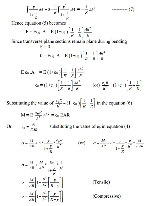
17 STATE THE STRESSES DUE TO
UNSYMMETRICAL BENDING
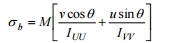
?b = bending stress in the curved bar
M
= moment due to the load applied
IUU = Principal moment of inertia in the
principal axes UU
I VV = Principal moment of inertia in
the principal axes VV
18 FATIGUE
Fatigue is defined as the failure of a
material under varying loads, well below the ultimate static load, after a
finite number of cycles of loading and unloading.
19 TYPES OF FATIGUE
STRESS
(i)
Direct stress
(ii)
Plane bending
(iii)
Rotating bending
(iv)
Torsion
(v)
Combined stresses
(a)
Fluctuating or alternating stress
(b)
Reversed stress.
20 STATE THE REASONS
FOR STRESS- CONCENTRATION
When a large stress gradient occurs in a
small, localized area of a structure, the
high stress is referred to as a stress concentration. The reasons for
stress concentration are
(i) discontinuities in continuum
(ii) contact forces.
21 CREEP
Creep can be defined as the slow and
progressive deformation of a material with
time under a constant stress.
Related Topics