Chapter: Electrical Engineering and Instrumentation : Analog and Digital Instruments
Storage oscilloscope
Storage oscilloscope
Oscilloscopes also come in analog and digital types. An analog oscilloscope works by directly applying a voltage being measured to an electron beam moving across the oscilloscope screen. The voltage deflects the beam up and down proportionally, tracing the waveform on the screen. This gives an immediate picture of the waveform as described in previous sections. In contrast, a digital oscilloscope samples the waveform and uses an analog-to-digital converter (or ADC) to convert the voltage being measured into digital information. It then uses this digital information to reconstruct the waveform on the screen For many applications either an analog or digital oscilloscope will do. However, each type does possess some unique characteristics making it more or less suitable for specific tasks. People often prefer analog oscilloscopes when it is important to display rapidly varying signals in "real time" (or as they occur). Digital oscilloscopes allow us to capture and view events that may happen only once. They can process the digital waveform data or send the data to a computer for processing. Also, they can store the digital waveform data for later viewing and printing.
Necessity for DSO and its Advantages
If an object passes in front of our eyes more than about 24 times a second over the same trajectory, we cannot follow the trace of the object and we will see the trajectory as a continuous line of action. Hence, the trajectory is stored in our physiological system. This principle is used in obtaining a stationary trace needed to study waveforms in conventional oscilloscopes. This is however, is not possible for slowly varying signals and transients that occur once and then disappear. Storage oscilloscopes have been developed for this purpose.
Digital storage oscilloscopes came to existence in 1971 and developed a lot since then. They provide a superior method of trace storage. The waveform to be stored is digitized, stored in a digital memory, and retrieved for displayed on the storage oscilloscope. The stored waveform is continuously displayed by repeatedly scanning the stored waveform. The digitized waveform can be further analyzed by either the oscilloscope or by loading the content of the memory into a computer. They can present waveforms before, during and after trigger. They provide markers, called the cursors, to help the user in measurements in annotation (detailing) of the measured values.
Principles of Operation
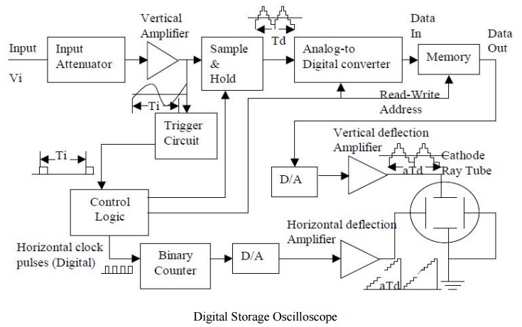
A simplified block diagram of a digital storage oscilloscope is shown below. The input circuitry of the DSO and probes used for the measurement are the same as the conventional oscilloscopes. The input is attenuated and amplified with the input amplifiers as in any oscilloscope. This is done to scale the input signal so that the dynamic range of the A/D converter can be utilized maximally. Many DSOs can also operate in a conventional mode, bypassing the digitizing and storing features. The output of the input amplifier drives the trigger circuit that provides signal to the control logic. It is also sampled under the control of the control logic. The sample and hold circuit takes the sample and stores it as a charge on a capacitor. Hence, the value of the signal is kept constant during the analog to digital conversion. The analog to digital converter (A/D) generates a binary code related to the magnitude of the sampled signal. The speed of the A/D converter is important and “flash” converters are mostly used. The binary code from the A/D converter is stored in the memory. The memory consists of a bank of random access memory (RAM) integrated circuits (ICs).
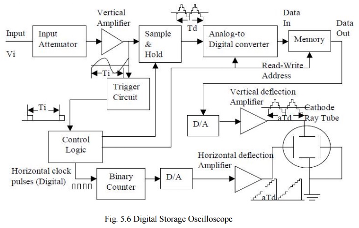
Block diagram of a digital storage oscilloscope
The Time-Base Circuit
The control logic generates a clock signal applied to the binary counter. The counter accumulates pulses and produces a binary output code that delivered to a digital to analog (D/A) converter to generate the ramp signal applied to the horizontal deflection amplifier. The horizontal deflection plates are supplied with this ramp signal to let the electron to travel across the screen horizontally at a constant speed. The speed of the transition of electron depends upon the slope of the ramp that is controlled by the clock rate. The capacity of the counter is taken to have the maximum number accumulated corresponding to the rightmost position on the screen. With the next clock pulse, the binary output of the counter drops to all zeros yielding the termination of the ramp.
The Displayed Signal
Meanwhile, the data currently in the store is read out sequentially and the samples pass to the second D/A converter. There they are reconstructed into a series of discrete voltage levels forming a stepwise approximation of the original waveform. This is fed to the vertical deflection plates via the vertical deflection amplifier. For a multi-trace oscilloscope, each channel has the same circuitry and outputs of the D/A converters are combined in the vertical deflection amplifier. The delay line used in conventional oscilloscopes for synchronization is not needed in digital storage oscilloscopes since this function can be easily handled by the control logic. The read out and display of samples constituting the stored waveform need not occur at the same sample rate that was used to acquire the waveform in the first place. It is sufficient to use a display sample rate adequate to ensure that each and every trace displayed is rewritten fifty or more times a second to prevent the flicker of the display. Eventually, the time interval of the signal on the display is not Td of the input signal. Assume that we have a sampling rate of 1000 samples per second and we use 1000 samples for the display. The time referred to the input signal is Td = 1 second and it takes 1 second for the DSO to store the information into the memory. Writing to the memory and reading from the memory are independent activities. Once the information is stored, it can be read at any rate.
Current Trends
The DSOs can work at low sweep rates allowing utilization of cheaper CRTs with wider screen and deflection yoke (coils that provide magnetic field instead of electrical field produced by the deflection plates). In some current DSOs, even liquid crystal displays (LCDs) are used with television like scanning techniques. This allows the development of hand-held and battery operated instruments. Some of these techniques will be dealt with in the section for display technologies.
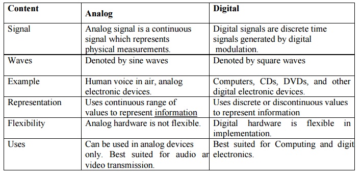
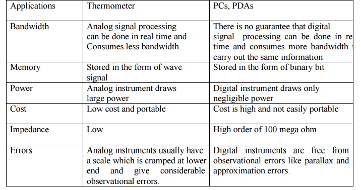
Comparison of analog and digital instruments
Related Topics