Chapter: Electrical Drives & Control : Conventional and Solid State Speed Control of A.C Drives
Slip Power Recovery Scheme
Slip Power Recovery Scheme:
Kramer System:
· It consists of main induction motor M, the speed of which is to be controlled.
· The two additional equipments are, d.c. motor and rotary converter.
· The d.c. side of rotary converter feeds a d.c. shunt motor commutator, which is directly connected to the shaft of the main motor.
· A separate d.c. supply is required to excite the field winding of d.c. motor and exciting winding of a rotary converter.
· The variable resistance is introduced in the field circuit of a d.c. motor which acts as s field regulator.
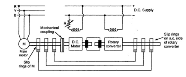
· The speed of the set is controlled by varying the field of the d.c. motor with the rheostat R. When the field resistance is changed, the back e.m.f. of motor changes.
· Thus the d.c. voltage at the commutator changes.
· This changes the d.c. voltage on the d.c. side of a rotary converter.
· Now rotary converter has a fixed ratio between its a.c. side and d.c. side voltages.
· Thus voltage on its a.c. side also changes. This a.c. voltage is given to the slip rings of the main motor.
· So the voltage injected in the rotor of main motor changes which produces the required speed control.
· Very large motors above 4000 kW such as steel rolling mills use such type of speed control.
· The main advantage of this method is that a smooth speed control is possible. Similarly wide range of speed control is possible.
· Another advantage of the system is that the design of a rotary converter is practically independent of the speed control required.
· Similarly if rotary converter is overexcited, it draws leading current and thus power factor improvement is also possible alongwith the necessary speed control.
Scherbius System:
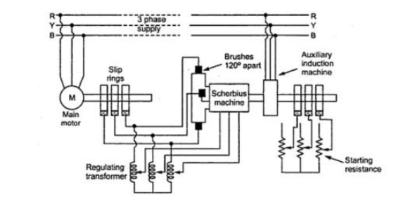
· This method requires an auxiliary 3 phase or 6 phase a.c. commutator machine which is called Scherbius machine.
· The difference between Kramer system and this system is that the Scherbius machine is not directly connected to the main motor, whose speed is to be controlled.
· The Scherbius machine is is excited at a slip frequency from the rotor of a main motor through a regulation transformer.
· The taps on the regulating transformer can be varied, this changes the voltage developed in the rotor Scherbius machine, which is injected into the rotor of main motor.
· This control the speed of the main motor, the scherbius machine is connected directly to the induction motor supplied from main line so that its speed deviates from a fixed value only to the extent of the slip of the auxiliary induction motor.
· For any given setting of regulating transformer, the speed of the main motor remains substantially constant irrespective of the load variations.
· Similar to the Kramer system, this method is also used to control speed of large induction motors.
· The only disadvantage is that these methods can be used only for slip ring induction motors.
Related Topics