Chapter: Mechanical Engineering : Refrigeration
Refrigeration
Refrigeration:
1 Vapour Compression Refrigeration System
2 Vapour Absorption Refrigeration System
3 Comparison Between Vapour Compression & Vapour Absorption Refrigeration Systems
REFRIGERATION:
·
It is defined as the process of providing and
maintaining a temperature well below that of surrounding atmosphere.
·
In other words refrigeration is the process
of cooling substance.
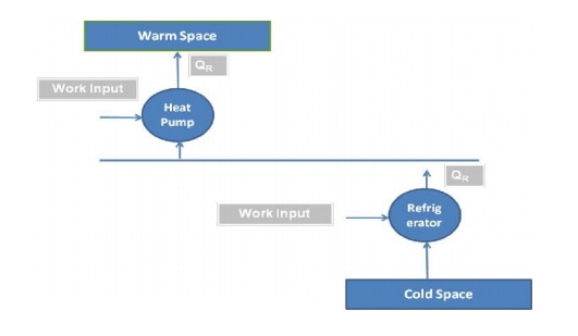
Refrigerators and heat pumps:
If the main purpose of the
machine is to cool some object, the machine is named as refrigerator.
If the main purpose of machine is to heat a medium
warmer than the surroundings, the machine is termed as heat pump.
Terminologies of Refrigeration:
Refrigerating
Effect (N):
It is defined as the quantity of heat extracted
from a cold body or space to be cooled in a given time.
N= Heat extracted from the cold space Time taken
Specific
Heat of water and ice :
It is the quantity of heat required to raise or
lower the temperature of one kg of water (or ice), through one kelvin or (10
c) in one second.
Specific
heat of water, Cpw = 4.19
kJ/kg K
Specific
heat of ice, Cpice = 2.1
kJ/kg K.
Capacity
of a Refrigeration Unit :
·
Capacity of a refrigerating machines are
expressed by their cooling capacity.
The standard unit used for expressing the capacity
of refrigerating machine is ton of refrigeration.
· One ton of refrigeration
is defined as, “the quantity of heat effect) to freeze one ton of
water Heat extracted from at oo c = latent heat of ice into one ton
of ice in a duration of 24 hours at 0o C”.
Latent
heat of ice= 336 kJ/kg i.e., 336 kJ of heat should be extracted one kg of water
at
0o C to convert it into ice.
One ton of refrigeration
= 336x1000 kJ/24 hrs. = 336x1000 kJ/min
=24x60
One ton of refrigeration
= 233.333 kJ/min
= 3.8889 kJ/sec
Co efficient of Performance
It is defined as the ratio of
heat extracted in a given time (refrigerating effect) to the work input.
Co efficient of performance = Heat extracted in
evaporator Work Input
Co
efficient of performance =
Refrigerating Effect
Work
Input
Co
efficient of performance = NW
The COP is always greater than 1 and known as theoretical
coefficient of performance.
Applications of Refrigeration:
In chemical industries, for separating and liquefying the
gases. In manufacturing and storing ice.
For the preservation of perishable food items in cold
storages. For cooling water.
For controlling humidity of air manufacture and heat treatment
of steels. For chilling the oil to remove wax in oil refineries.
For the preservation of tablets and medicines in
pharmaceutical industries. For the preservation of blood tissues etc.,
For comfort air conditioning the hospitals, theatres, etc.,
Properties
of Refrigeration:
A good refrigerant should have high latent heat of
vapourisation. It should have low boiling and low freezing point.
It should be non toxic and should non corrosiveness It should
be non flammable and non explosive.
It should have high thermal conductivity It should be easy to
handle
It should have low specific volume of vapour. It should have
high co efficient of performance
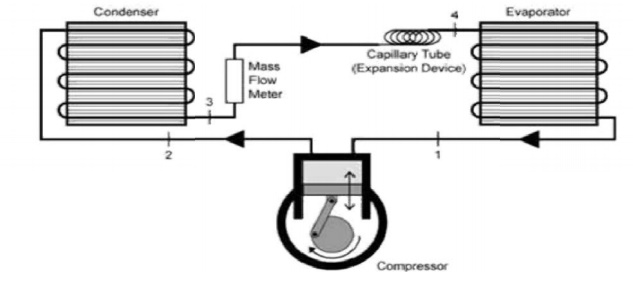
VAPOUR COMPRESSI ON REFRIGERATION SYSTEM
Construction:
This system consists o f a compressor, condenser, a receiver
tank, a n expansion valve and an evaporato r.
Compressor : Recipro cating compressors
generally used. For very big plants centrifugal compressor s directly
coupled with high speed rotating engi nes (gas turbine) are used.
For very big
plantsC entrifugal
compressors directly coupled
with high speed rotating engines (gas turbine) are used
Condenser : It is a coil of tubes made
of copper.
Receiver tank: It is the reservoir of
liquid refrigerant.
Expansion Valve: Thi s is
a throttle valve. High pressure refrigerant is made to flow at a
controlled rate through this valve.
Evaporator : It is the actual cooler
and kept in the space to be cooled. The evaporator is a coil of tubes
made of copper
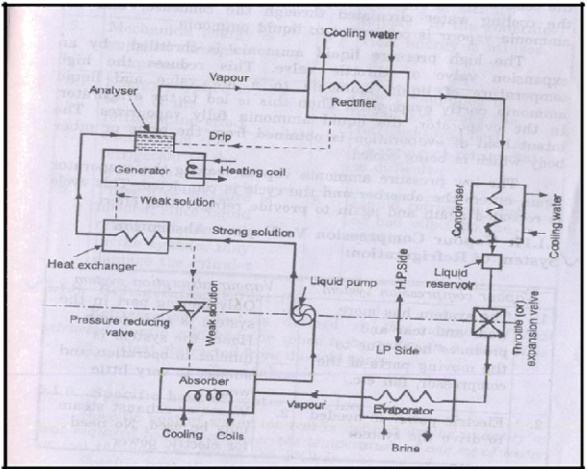
VAPOUR ABSORPTION REFRIGERATION SYSTEM:
Construction:
The vapour absorption system consists of a condenser, an
expansion valve and an evaporator.
They perform the same as t hey do
in vapour compression method.
In addition to these, this system has an absorber, a heat
exchanger, an analyser and a rectifier.
Working:
•
Dry ammonia vapour at low pressure passes in to
the absorber from the evaporator.
•
In the absorber the d ry ammonia vapour is
dissolved in cold water and strong solution of ammonia is formed.
•
Heat evolved during the absorption of ammonia is
removed by cir culating cold water through the coils kept in the absorber.
The highly concentrated ammonia (known as Aqua Ammonia) is
then pumped by a pump to generator through a heat exchanger.
•
In the heat exchanger the strong ammonia solution
is heated by the h ot weak solution returning from the generator to the
absorber.
•
In the generator the w arm solution is further
heated by steam coils, gas or electricity
and the
ammonia vapour is driven out of solution.
• The boiling point of a mmonia is
less than that of water.
•
Hence the vapours le aving the generator are
mainly of ammonia.
•
The weak ammonia solution is left in the generator
is called weak aq ua.
• This weak
solution is returned to the absorber through the heat exchan ger.
•
Ammonia vapours le aving the generator may contain
some water vap our.
•
If this water vapour i s allowed to the condenser
and expansion valv e, it may freeze resulting in chocked f low.
•
Analyser and rectifier s are incorporated in the
system before condenser.
•
The ammonia vapour from the generator passes
through a series of trays in the analyser and ammonia is separated from water
vapour.
•
The separated water v apour returned to generator.
• Then the ammonia va pour passes
through a rectifier.
• The rectifier
resembles a condenser
and water vapour
still prese nt in
ammonia
vapour
condenses andd the condensate is returned to analyser.
•
The virtually pure am monia vapour then passes
through the condense r.
•
The
latent heat of
ammonia vapour is
rejected to the
cooling water circulated
through
the condenser and the ammonia vapour is condensed to liquid ammonia.
• The high
pressure liquid ammonia is throttled by an expansion v alve or throttle valve.
•
This reduces the high temperature of the liquid
ammonia to a low value and liquid ammonia partly evaporates.
•
Then this is led to the evaporator.
•
In the evaporator the liquid fully vaporizes.
•
The latent heat of evaporation is obtained from
the brine or other body which is being cooled.
•
The low pressure ammonia vapour leaving the
evaporator again enters the absorber and the cycle is completed.
•
This cycle is repeated again to provide the
refrigerating effect.
Applications
of refrigeration system:
·
Preservation of food items like vegetables,
milk and eggs.
·
Preservation of medicines.
·
Preservation of blood, tissues, etc.,
·
Preservation and cooling of cool drinks.
·
Preservation of chemicals (Chemical
industries)
·
Cooling of water.
·
Industrial and comfort airconditioning.
·
Processing of dairy products.
COMPARISON BETWEEN VAPOUR COMPRESSION & VAPOUR
ABSORPTION REFRIGERATION SYSTEMS:
Vapour
Compression System
1. This system has more wear and tear and produces more noise due to the moving
parts of the compressor.
2. Electric power is needed to drive the system
3. Capacity of the system drops rapidly with lowered
evaporator pressure
4. At partial loads performance is poor.
5. Mechanical energy is supplied through compressor
6. Energy supplied is ¼ to ½ of the refrigerating effect
7. Charging of the refrigerating to the system is easy
8. Preventive measure is needed, since liquid refrigerant
accumulated in the cylinder may damage to the cylinder
Vapour
Absorption System
1. Only moving part in this system is an aqua pump. Hence the
quieter in operation and less wear and tear
2. Waste of exhaust steam may be used. No need of electric
power
3. Capacity of the system decreases with the lowered
evaporative pressure, by increasing the steam pressure in generator.
4. At partial loads performance is not affected.
5. Heat energy is utilized
6. Energy supplied is about one and half times the
refrigerating effect
7. Charging of refrigerant is difficult
8. Liquid refrigerant has no bad effect on the system.
Related Topics