Chapter: Automation, Production Systems, and Computer Integrated Manufacturing : Group Technology and Cellular Manufacturing
Parts Classification and Coding
PARTS CLASSIFICATION AND CODING
This is
the most time consuming of the three methods. In parts classification and coding, similarities among parts are
identified, and these similarities are related in a coding system. Two
categories of part similarities can be distinguished: (1) design attributes, which arc concerned with part characteristics
such as geometry, size, and material; and (2) manufacturing attributes, which consider the sequence of processing
steps required to make a part. While
the design and manufacturing attributes of a part are usually correlated, the
correlation is less than perfect. Accordingly, classification and coding
systems are devised to include both a part's design attributes and its
manufacturing attributes. Reasons for using a coding scheme include:
Design
retrieval. A designer faced with the task of developing a new
part can use a design retrieval system
to determine if a similar part already exists. A simple change in an existing
part would take much less time than designing a whole new part from scratch.
Automated
process planning. The part code for a new part can be used to search
for process plans for existing parts
with identical or similar codes
Machine
cell design. The part codes can be used to design machine cells
capable of producing all members of a
particular part family, using the composite part concept (Section 15.4.1).
To
accomplish parts classification and coding requires examination and analysis of
the design and/or manufacturing attributes of each part. The examination is
sometimes done
by
looking in tables to match the subject part against the features described and
diagrammed in the tables. An alternative and more-productive approach involves
interaction with a computerized classification and coding system, in which the
user responds to questions asked by the
computer. On the basis of the responses, the computer assigns the code number
to the part. Whichever method is used, the classification results in a code
number that uniquely identifies the part's attributes.
The
classification and coding procedure may be carried out on the entire list of
active parts produced by the firm, or some sort of sampling procedure may be
used to establish part families. For example, parts produced in the shop during
a certain time period could be examined to identify part family categories. The
trouble with any sampling procedure is the risk that the sample may be
unrepresentative of the population.
A number
of classification and coding systems are described in the literature [13],
[16], [31], and there are a number of commercially available coding packages.
However, none of the systems has been universally adopted. One of the reasons
for this is that a classification and coding system should be customized for it given company or industry. A
system that is best for one company may not be best for another company.
Features of Parts Classification and Coding
Systems
The
principal functional areas that utilize a parts classification and coding
system are design and manufacturing. Accordingly. parts classification systems
fall into one of three categories;
systems based
on part design attributes
systems
based on part manufacturing attributes
systems
based on both design and
manufacturing attributes
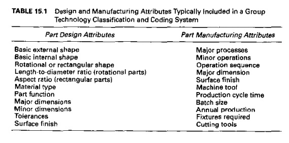
Table
15.1 presents a list of the common design and manufacturing attributes
typically included in classification schemes. A certain amount of overlap
exists between design and manufacturing attributes, since a part's geometry is
largely determined by the sequence of manufacturing processes performed on it.
In terms
of the meaning of the symbols in the code, there are three structures used in
classification and coding schemes:
hierarchical
structure, also known as a
monocode, in which the interpretation of each successive symbol depends on the value of the preceding symbols
Chain-type
structure, also known as a
polycode, in which the interpretation of each symbol in the sequence is always the same; it does not depend on
the value of preceding symbols
mixed-mode
structure. which is a
hybrid of the two previous codes
To
distinguish the hierarchical and chain-type structures, consider a two-digit
code number for a part, such as 15 or 25. Suppose the first digit stands for
the general shape of the part: 1 means the part is cylindrical (rotational),
and 2 means the geometry is rectangular.
In a hierarchical structure, the interpretation of the second digit depends on the value of the first digit. If preceded by 1, the 5 might indicate a length to diameter ratio; and if preceded by 2, the 5 indicates an aspect ratio between the length and width dimensions of the part. In the chain-type structure, the symbol 5 would have the same meaning whether preceded by 1 or 2. For example, it might indicate the overall length of the part. The advantage of the hierarchical structure is that in general. more information can he included in a code of a given number of digits.
The
number of digits in the code can range from 6 to 30. Coding schemes that
contain only design data require fewer digits. perhaps 12 or fewer. Most modem
classification and coding systems include both design and manufacturing data,
and this usually requires 2030 digits. This might seem like too many digits fur
a human reader to easily comprehend, but it must be remembered that most of the
data processing of the codes is accomplished by computer. for which a large
number of digits is of minor concern
Examples of
Parts Classification and Coding Systems
Some of
the important systems (with emphasis on those in the United States) include: the
Opitz classification system, which is nonproprietary; the Brisch System (Brisch-Birn,
Inc.); CODE (Manufacturing Data Systems. lnc.]: CUTPLAN (Metcut Associates);
DCLASS (Brigham Young University): Multi-Class (OIR: Organization for
Industrial Research);and Part Analog System (Lovelace. Lawrence & Co., Inc.). Reviews of these
systems and others can be found in [161 and [23].
In the
following. we discuss two classification and coding systems: the Opitz System
and Multi-Class. The Opitz system is 0' interest because it was one of the
first published classification and coding schemes for mechanical parts [31]
(Historical Note 15.1) and is still widely used. MultiClass is a commercial
product offered by the Organization for Industrial Research (OIR)
Opitz
Classification System. This system was developed by H. Opitz of the
University of Aachen in Germany. It represents one of the pioneering efforts in
group technology and is probably the best known, if not the most frequently
used, of the parts classification and coding systems. It is intended for
machined parts. The Opitz coding scheme uses thc following digit sequence:
12345 6789 ABCD
The basic
code consists of nine digits, which can be extended by adding four more digits.
The first nine arc intended to convey both design and manufacturing data. The
interpretation of the first nine digits is defined in Figure 15.5. The first
five digits, 12345, are called the form
code. It describes the primary design attributes of the part, such as
external shape (e.g., rotational vs.
rectangular) and machined features (e.g., holes, threads, gear teeth, etc.].
The next four digits, 6789, constitute the supplementary
code, which indicates some of the attributes that would be of use in
manufacturing (e.g., dimensions, work material, starting shape, and accuracy).
The extra four digits, ABCD, are referred to as the secondary code and are intended to identify the production
operation type and sequence. The secondary code can be designed by the user
firm to serve its own particular needs.
The
complete coding system is too complex to provide a comprehensive description
here. Opitz wrote an entire book on his system [31]. However, to obtain a general
idea of how it works, let us examine the form code consisting of the first five
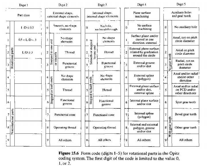
digits. defined generally in Figure 15.5. The first digit identifies whether
the part is rotational or nonrotational.1t also describes the general shape and
proportions of the part. We limit our survey here to rotational parts
possessing no unusual features, those with first digit values of O, 1,
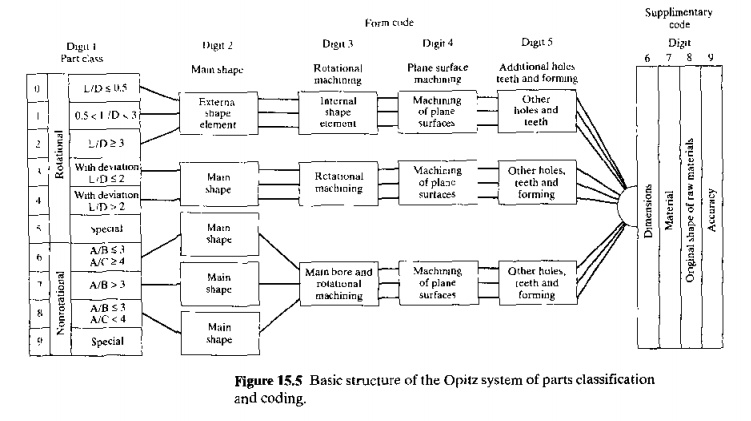
Or 2. For
this etas, of work parts, the coding of the first five digits is defined in
Figure 15,6. Consider the following example to demonstrate the coding of a
given part.
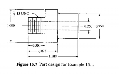
EXAMPLE
15.1 Opitz Part Coding System
Given the
rotational part design in Figure 15.7, determine the form code in the Opitz
parts classification and coding system
Solution:
With reference to Figure 15.6, the
fivedigit code is developed as follows:
Lengthtodiameter
ratio, LID = 1.5 Digit 1 = 1
External
shape: stepped on both ends with screw
thread on one end Digit 2 = 5
Internal
shape: part contains a throughhole Digit 3 ==
1
Plane
surface machining: none Digit 4 == 0
Auxiliary
holes, gear teeth, etc.: none Digit 5 =
0
The form
code in the Opitz system is 15100.
MultiClass.
MultiClass
is a classification and coding system developed by the Organization for
Industrial Research (OIR). The system is relatively flexible, allowing the user
company to customize the classification and COlling scheme 10 a large extent to
fit its own products and applications. Multi Class can be used for a variety of
different types of manufactured items, including machined and sheer metal
parts, tooling, electronics, purchased
parts, assemblies
and subassemblies, machine tools, and other elements.
Up to nine different types of components
can be included within a single MultiClass software structure
MultiClass uses a hierarchical or decision-tree coding
structure in which the succeeding digits depend
on values of the previous digits. In the application of the system, a series of menus, pick lists,
tables, and other interactive prompting
routines are used to code the
part. This helps to organize and provide discipline to the coding procedure.
The
coding structure consists of up to 30 digits. These are divided into two
regions, one provided by GIR, and the second designed by the user to meet specific needs
and requirements. A prefix precedes the code number and is used to identify the
type of part (e.g., a prefix value of 1 indicates machined and sheet metal
parts). For a machined part, the coding for the first 18 digit positions (after
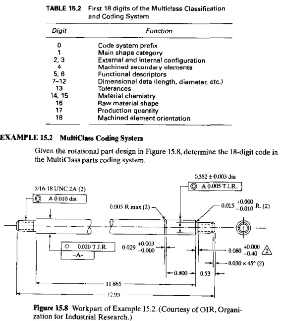
the prefix) is summarized in Table 15.2.
TABLE 15.2 First 18 digits of the Multiclass
Classification and Coding System
Digit Function
o Code
system preflx
1 Main
shape category
2,3 External
and internal configuration
4 Machined
secondary elements
5,6 Functional
descriptors
712 Dimensional data !length, diameter, etc.)
13 Tolerances
14,15 Material
chemistry
Raw
material shape
Production quantity
Machined
element orientation
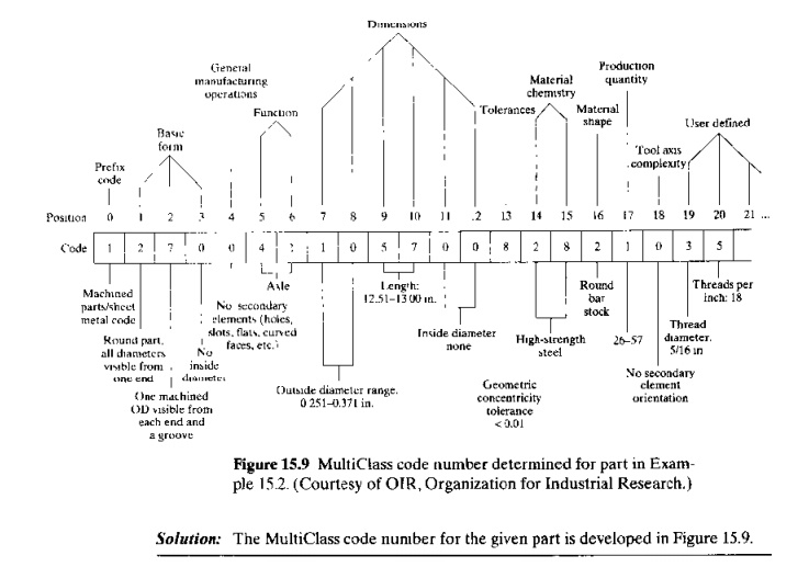
EXAMPLE 15.2 MuitiClass
Coding System
Given the
rotational part design in Figure 15.8, determine the IS digit code in the
MultiClass parts coding system.
Related Topics