Chapter: Power Quality : Voltage Sags and Interruptions
Mitigation of Voltage Sags
Mitigation of Voltage Sags:
ü Different
power quality problems would require different solution. It would be very
costly to decide on mitigate measure that do not or partially solve the
problem.
ü These
costs include lost productivity, labor costs for clean up and restart, damaged
product, reduced product quality, delays in delivery and reduced customer
satisfaction.
ü When a
customer or installation suffers from voltage sag, there is a number of
mitigation methods are available to solve the problem.
ü These
responsibilities are divided into three parts that involves utility, customer
and equipment manufacturer.
ü Different
mitigation methods are
o Dynamic voltage restorer
o Active series Compensators
o Distribution
static compensator (DSTATCOM) o Solid state transfer switch (SSTS)
o Static UPS with energy storage
o Backup
storage energy supply (BSES) o Ferro resonant transformer
o Flywheel and Motor Generator set
o
Static Var Compensator (SVC)
1. Dynamic Voltage Restorer:
(DVR)
ü Dynamic
Voltage Restorers (DVR) are complicated static devices which work by adding the
‘missing’ voltage during a voltage sag. Basically this means that the device
injects voltage into the system in order to bring the voltage back up to the
level required by the load.
ü Injection
of voltage is achieved by a switching system coupled with a transformer which
is connected in series with the load.
ü There are
two types of DVRs available; those with and without energy storage. Devices
without energy storage are able to correct the voltage waveform by drawing
additional current from the supply.
ü Devices
with energy storage use the stored energy to correct the voltage waveform. The
difference between a DVR with storage and a UPS is that the DVR only supplies
the part of the waveform that has been reduced due to the voltage sag, not the
whole waveform.
ü In
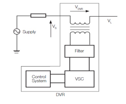
addition, DVRs generally cannot operate during interruptions. Figure 10 shows a
schematic of a DVR.
ü As can be
seen the basic DVR consists of an injection/booster transformer, a harmonic
filter, a voltage source converter (VSC) and a control system.
ü For
readers who are interested in further knowledge of DVR systems, the article in
gives a thorough description of the design and operation of DVRs. DVR systems
have the advantage that they are highly efficient and fast acting. It is
claimed in that the DVR is the best economic solution for mitigating voltage
sags based on its size and capabilities.
ü In the
case of systems without storage, none of the inherent issues with storage are
relevant. Another advantage of DVR systems is that they can be used for
purposes other than just voltage sag mitigation.
2. Ferro Resonant Transformer:
ü A Ferro
resonant transformer, also known as a constant voltage transformer (CVT), is a
transformer that operates in the saturation region of the transformer B-H
curve.
ü Voltage
sags down to 30 % retained voltage can be mitigated through the use of Ferro
resonant transformers.
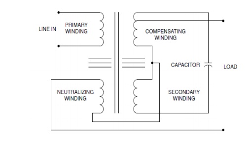
ü Figure
shows a schematic of a Ferro resonant transformer. The effect of operating the
transformer in this region is that changes in input voltage only have a small
impact on the output voltage.
ü Ferro
resonant transformers are simple and relatively maintenance free devices which
can be very effective for small loads. Ferro resonant transformers are
available in sizes up to around 25 KVA.
ü On the
down side, the transformer introduces extra losses into the circuit and is
highly inefficient when lightly loaded. In some cases they may also introduce
distorted voltages.
ü In
addition, unless greatly oversized, Ferro resonant transformers are generally
not suitable for loads with high inrush currents such as direct-on-line motors.
3. Uninterrupted Power Supply
(UPS):
ü Uninterruptible
power supplies (UPS) mitigate voltage sags by supplying the load using stored
energy. Upon detection of voltage sag, the load is transferred from the mains
supply to the UPS.
ü Obviously,
the capacity of load that can be supplied is directly proportional to the
amount of energy storage available.
ü UPS
systems have the advantage that they can mitigate all voltage sags including
outages for significant periods of time (depending on the size of the UPS).
ü There are
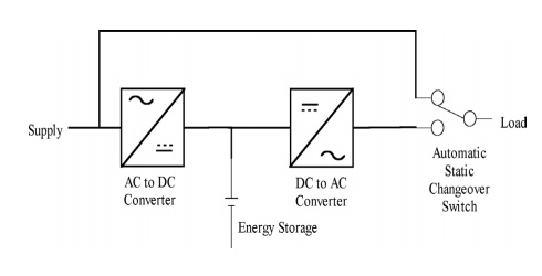
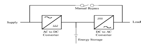
2 topologies of UPS available; on-line and off-line. Figure 1 shows a schematic
of an off-line UPS while Figure 2 shows a schematic of an on-line UPS.
ü Comparison
of the figures shows that the difference between the two systems is that for an
on-line UPS the load is always supplied by the UPS, while for off-line systems;
the load is transferred from the mains supply to the UPS by a static changeover
switch upon detection of voltage sag.
ü The lack
of a changeover switch renders the on-line system more reliable as any failure
of the changeover switch will result in the off-line UPS being ineffective. UPS
systems have disadvantages related to energy storage components (mostly
batteries) which must be maintained and replaced periodically.
ü Small UPS
systems are relatively simple and cheap. However, large units are complex and
highly expensive due to the need for large energy storage capacities.
Block Diagram of Offline UPS:
Block Diagram of Online UPS:
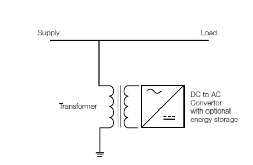
4. Static Var Compensator(SVC):
ü A SVC is
a shunt connected power electronics based device which works by injecting
reactive current into the load, thereby supporting the voltage and mitigating
the voltage sag.
ü SVCs may
or may not include energy storage, with those systems which include storage
being capable of mitigating deeper and longer voltage sags.
Block Diagram of SVC:
Related Topics