Chapter: RF and Microwave Engineering : Microwave Passive Components
Microwave Passive Components
MICROWAVE PASSIVE COMPONENTS
1. MICROWAVE FREQUENCY RANGE:
Microwaves are electromagnetic waves with wavelengths ranging from 1 mm to 1 m, or frequencies between 300 MHz and 300 GHz.
L band 1 to 2 GHz
S band 2 to 4 GHz
C band 4 to 8 GHz
X band 8 to 12 GHz
Ku band 12 to 18GH GHz
K band 18 to 26.5 GHz
Ka band 26.5 to 40 GHz
Q band 30 to 50 GHz
U band 40 to 60 GHz
V band 50 to 75 GHz
2: SIGNIFICANCE MICROWAVE FREQUENCY RANGE:
Wireless LAN protocols, such as Bluetooth and the IEEE 802.11 specifications, also use microwaves in the 2.4 GHz ISM band, although 802.11a uses ISM band and U-NII frequencies in the 5 GHz range. Licensed long-range (up to about 25 km) Wireless Internet Access services can be found in many countries (but not the USA) in the 3.5–4.0 GHz range. Metropolitan Area Networks: MAN protocols, such as WiMAX (Worldwide Interoperability for Microwave Access) based in the IEEE 802.16 specification. The IEEE 802.16 specification was designed to operate between 2 to 11 GHz. The commercial implementations are in the 2.3GHz, 2.5 GHz, 3.5 GHz and 5.8 GHz ranges.
Wide Area Mobile Broadband Wireless Access: MBWA protocols based on standards specifications such as IEEE 802.20 or ATIS/ANSI HC-SDMA (e.g. iBurst) are designed to operate between 1.6 and 2.3 GHz to give mobility and in-building penetration characteristics similar to mobile phones but with vastly greater spectral efficiency.
Cable TV and Internet access on coaxial cable as well as broadcast television use some of the lower microwave frequencies. Some mobile phone networks, like GSM, also use the lower microwave frequencies.
3 :APPLICATION OF MICROWAVE:
1.FM Brodcasting
2.CDMA mobile phone
3.GSM Mobile phone
4. Cable television relay
5.Geostationary fixed satellite service
6.Marine airborne radar
7.Remote sensing radar
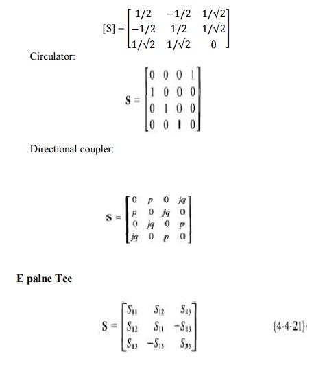
4: SCATTERING MATRIX:
"Scattering" is an idea taken from billiards, or pool. One takes a cue ball and fires it up the table at a collection of other balls. After the impact, the energy and momentum in the cue ball is divided between all the balls involved in the impact. The cue ball "scatters" the stationary target balls and in turn is deflected or "scattered" by them.
In a microwave circuit, the equivalent to the energy and momentum of the cue ball is the amplitude and phase of the incoming wave on a transmission line. (A rather loose analogy, this). This incoming wave is "scattered" by the circuit and its energy is partitioned between all the possible outgoing waves on all the other transmission lines connected to the circuit. The scattering parameters are fixed properties of the (linear) circuit which describe how the energy couples between each pair of ports or transmission lines connected to the circuit.
Formally, s-parameters can be defined for any collection of linear electronic components, whether or not the wave view of the power flow in the circuit is necessary. They are algebraically related to the impedance parameters (z-parameters), also to the admittance parameters (y-parameters) and to a notional characteristic impedance of the transmission lines.
5. COCEPT OF N PORT SCATTERING MATRIX REPRESENTATION:
An n-port microwave network has n arms into which power can be fed and from which power can be taken. In general, power can get from any arm (as input) to any other arm (as output). There are thus n incoming waves and n outgoing waves.
We also observe that power can be reflected by a port, so the input power to a single port can partition between all the ports of the network to form outgoing waves. Associated with each port is the notion of a "reference plane" at which the wave amplitude and phase is defined.
Usually the reference plane associated with a certain port is at the same place with respect to incoming and outgoing waves. The n incoming wave complex amplitudes are usually designated by the n complex quantities an, and the n outgoing wave complex quantities are designated by the n complex quantities bn. The incoming wave quantities are assembled into an n-vector
A and the outgoing wave quantities into an n-vector B. The outgoing waves are expressed in terms of the incoming waves by the matrix equation B = SA where S is an n by n square matrix of complex numbers called the "scattering matrix". It completely determines the behaviour of the network. In general, the elements of this matrix, which are termed "s-parameters", are all frequency-dependent.
For example, the matrix equations for a 2-port are
b1 = s11 a1 + s12 a2
b2 = s21 a1 + s22 a2
And the matrix equations for a 3-port are
b1 = s11 a1 + s12 a2 + s13 a3
b2 = s21 a1 + s22 a2 + s23 a3
b3 = s31 a1 + s32 a2 + s33 a3
The wave amplitudes an and bn are obtained from the port current and voltages by the relations a = (V + ZoI)/(2 sqrt(2Zo)) and b = (V - ZoI)/(2 sqrt(2Zo)). Here, a refers to an if V is Vn and I In for the nth port. Note the sqrt(2) reduces the peak value to an rms value, and the sqrt(Zo) makes the amplitude normalised with respect to power, so that the incoming power = aa* and the outgoing power is bb*.
A one-port scattering parameter s is merely the reflection coefficient gamma, and as we have seen we can relate gamma to the load impedance zL = ZL/Zo by the formula gamma = (zL-1)/(zL+1).
Similarly, given an n by n "Z-matrix" for an n-port network, we obtain the S matrix from the formula S = (Z-I)(Z+I)^-1, by post-multiplying the matrix (Z-I) by the inverse of the matrix (Z+I). Here, I is the n by n unit matrix. The matrix of z parameters (which has n squared elements) is the inverse of the matrix of y parameters.
6. PROPRTIES OF S MATRIX
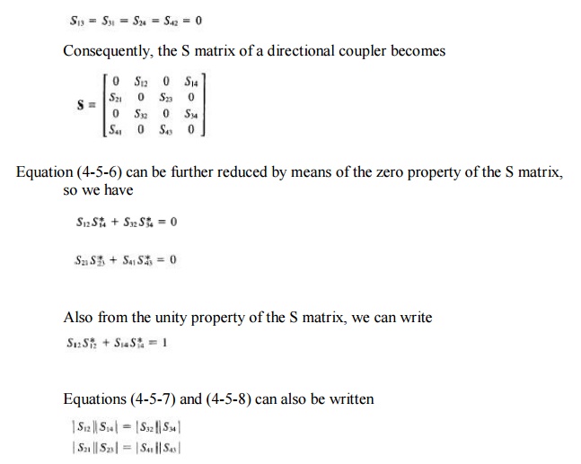
1) Zero diagonal elements for perfect matched network
For an ideal network with matched termination Sii=0, since there is no refiection from any port. Therefore under perfect matched condition yhe diagonal element of [s] are zero
2) Symmetry of [s] for a reciprocal network
The reciprocal device has a same transmission characteristics in either direction of a pair of ports and is characterized by a symmetric scattering matrix
Sij = Sji ; i≠j Which results [S] t = [S]
For a reciprocal network with assumed normalized the impeadence matrix equation is
[b] = ( [z] + [u] )-1 ([z] – [u]) [a] -----------(1)
Where u is the unit matrix
S matrix equation of network is [b] = [s] [a] ------------(2)
Compare equ (1) & (2)
[s] =([z]+[u])-1 ([z] – [u])
[R] = [Z] – [U]
[Q] = [Z] + [U]
For a reciprocal network Z matrix Symmetric
[R] [Q] = [Q] [R]
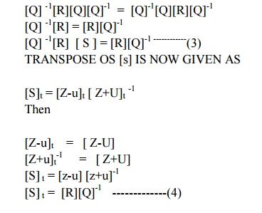
When compare 3 & 4
[S] t = [S]
3) Unitary property of lossless network
For any loss less network the sum of product of each term of any one row or any one column of s matrix multiplied by its complex conjugate is unity
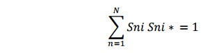
or a lossless N port devices the total power leaving N ports must be equal to total input to the ports
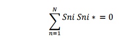
4) Zero property
It states that the sum of the product of any each term of any one row or any one column of a s matrix is multiplied by the complex conjucate of corresponding terms of any other row is zero
5) Phase shift propert
If any of the terminal or reference plane are mover away from the junction by an electric
distance βk, lk. each of the coefficient Sij involving K will be multiplied by the factor (e –jβk/k)
7. S MATRIX FORMULATION OF TWO PORT JUNCTION
In the case of a microwave network having two ports only, an input and an output, the s-matrix has four s-parameters, designated s11 s12 s21 s22
These four complex quantites actually contain eight separate numbers; the real and imaginary parts, or the modulus and the phase angle, of each of the four complex scattering parameters. Let us consider the physical meaning of these s-parameters. If the output port 2 is terminated, that is, the transmission line is connected to a matched load impedance giving rise to no reflections, then there is no input wave on port 2.
The input wave on port 1 (a1) gives rise to a reflected wave at port 1 (s11a1) and a transmitted wave at port 2 which is absorbed in the termination on 2.
The transmitted wave size is (s21a1). If the network has no loss and no gain, the output power must equal the input power and so in this case |s11|^2 + |s21|^2 must equal unity. We see therefore that the sizes of S11 and S21 determine how the input power splits between the possible output paths.
8. MICROWAVE JUNCTIONS:
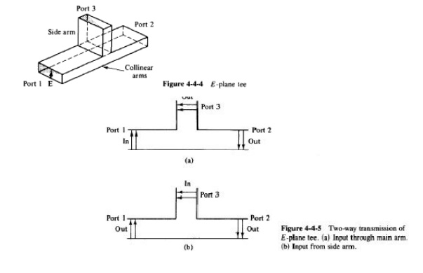
E PLANE TEE
H PLANE TEE
MAGIC TEE OR HYPRID TEE
9. TEE JUNCTIONS:
Tee junctions. In microwave circuits a waveguide or coaxial-line junction with three independent ports is commonly referred to as a tee junction.
From the S parameter theory of a microwave junction it is evident that a tee junction should be characterized by a matrix of third order containing nine elements, six of which should be independent.
The characteristics of a three-port junction can be explained by three theorems of the tee junction. These theorems are derived from the equivalent- circuit representation of the tee junction. Their statements follow
1. A short circuit may always be placed in one of the arms of a three-port junction in such a way that no power can be transferred through the other two arms.
2. If the junction is symmetric about one of its arms, a short circuit can always be placed in that arm so that no reflections occur in power transmission between the other two arms. (That is, the arms present matched impedances.)
3. It is impossible for a general three-port junction of arbitrary symmetry to present matched impedances at all three arms.
H-plane tee (shunt tee). An H -plane tee is a waveguide tee in which the axis of its side arm is "shunting" the E field or parallel to the H field of the main guide as shown in Fig.
It can be seen that if two input waves are fed into port 1 and port 2 of the collinear arm, the output wave at port 3 will be in phase and additive. On the other hand, if the input is fed into port 3, the wave will split equally into port 1 and port 2 in phase and in the same magnitude.
Therefore the S matrix of the H -plane tee is similar to Eqs.
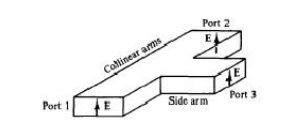
E -plane tee {series tee). An E -plane tee is a waveguide tee in which the axis of its side arm is parallel to theE field of the main guide
If the collinear arms are symmetric about the side arm, there are two different transmission characteristics
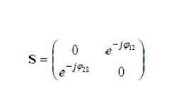
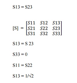
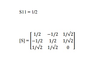
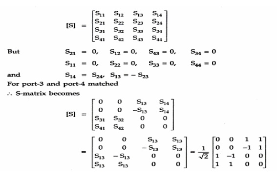
It can be seen from Fig. 4-4-4 that if the Eplane tee is perfectly matched with the aid of screw tuners or inductive or capacitive windows at the junction, the diagonal components of the scattering matrix, S1~, Szz, and S33, are zero because there will be no reflection.
When the waves are fed into the side arm (port 3), the waves appearing at port 1 and port 2 of the collinear arm will be in opposite phase and in the same magnitude. Therefore It should be noted that Eq. does not mean that SI3 is always positive and S23
is always negative. The negative sign merely means that Sl3 and S23 have opposite signs. For a matched junction, the S matrix is given by
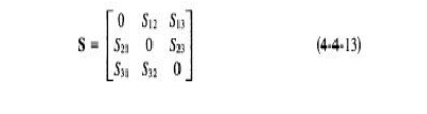
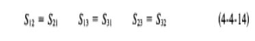
From the symmetry property of S matrix, the symmetric terms in Eq. ( 4-4-I3) are equal and they are
From the zero property of S matrix, the sum of the products of each term of any column (or row) multiplied by the complex conjugate of the corresponding terms of any other column (or row) is zero and it is

This means that either Sl3 or St3, or both, should be zero. However, from the unity property of S matrix, the sum of the products of each term of any one row (or column) multiplied by its complex conjugate is unity; that is,
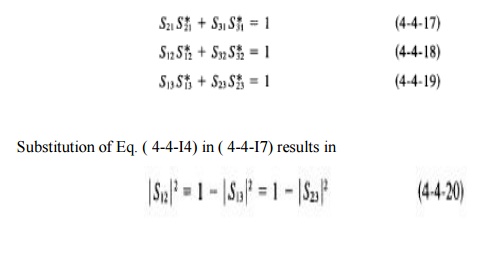
zero and thus Eq. ( 4-4-19) is false. In a similar fashion, if S23 = 0, then S 13 becomes zero and therefore Eq. (4-4-20) is not true.
This inconsistency proves the statement that the tee junction cannot be matched to the three arms. In other words, the diagonal elements of the S matrix of a tee junction are not all zeros.
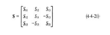
In general, when an £-plane tee is constructed of an empty waveguide, it is poorly matched at the tee junction. Hence SiJ * 0 if i = j.
However, since the collinear arm is usually symmetric about the side arm, I S13l = I S23l and S11 = S22. Then the S matrix can be simplified to
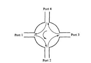
10. MAGIC TEE:
A magic tee is a combination of the E -plane tee and H -plane tee (refer to Fig. 4-4-7). The magic tee has several characteristics:
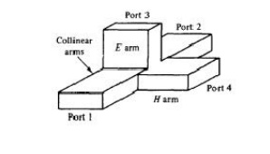
1. If two waves of equal magnitude and the same phase are fed into port 1 and port 2, the output will be zero at port 3 and additive at port 4.
2. If a wave is fed into port 4 (the Harm), it will be divided equally between port 1 and port 2 of the collinear arms and will not appear at port 3 (the E arm).
3. If a wave is fed into port 3 (the E arm), it will produce an output of equal magnitude and opposite phase at port 1 and port 2. The output at port 4 is zero. That is, S43 = S34 = 0.
4. If a wave is fed into one of the collinear arms at port 1 or port 2, it will not appear in the other collinear arm at port 2 or port 1 because the E arm causes a phase delay while the Harm causes a phase advance. That is, S,z = Sz1 = 0.
Therefore the S matrix of a magic tee can be expressed as
The magic tee is commonly used for mixing, duplexing, and impedance measurements. Suppose, for example, there are two identical radar transmitters in equipment stock.
A particular application requires twice more input power to an antenna than either transmitter can deliver. A magic tee may be used to couple the two transmitters to the antenna in such a way that the transmitters do not load each other.
The two transmitters should be connected to ports 3 and 4, respectively, as shown in Fig. 4-4-8. Transmitter 1, connected to port 3, causes a wave to emanate from port 1 and another to emanate from port 2; these waves are equal in magnitude but opposite in phase.
Similarly, transmitter 2, connected to port 4, gives rise to a wave at port 1 and another at port 2, both equal in magnitude and in phase.
At port 1 the two opposite waves cancel each other. At port 2 the two in-phase waves add together; so double output power at port 2 is obtained for the antenna as shown in Fig. 4-4-8.
11. RATE RACE –CORNERS
Applications of rat-race couplers are numerous, and include mixers and phase shifters. The rat-race gets its name from its circular shape, shown below. The circumference is 1.5 wavelengths. For an equal-split rat-race coupler, the impedance of the entire ring is fixed at 1.41xZ0, or 70.7 ohms for a 50 ohm system. For an input signal Vin, the outputs at ports 2 and 4 (thanks, Tom!) are equal in magnitude, but 180 degrees out of phase.
The coupling of the two arms is shown in the figure below, for an ideal rat-race coupler centered at 10 GHz (10,000 MHz). An equal power split of 3 dB occurs at only the center frequency. The 1-dB bandwidth of the coupled port (S41) is shown by the markers to be 3760 MHz, or 37.6 percent.
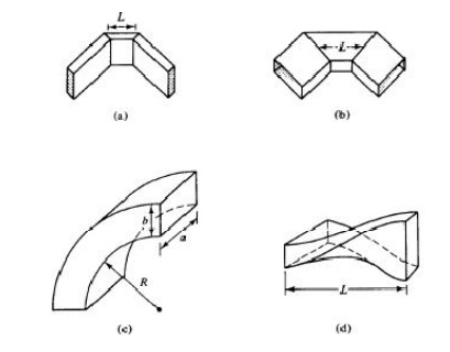
12. BENTS &TWISTS:
The waveguide corner, bend, and twist are shown in Fig. 4-4-10. These waveguide components are normally used to change the direction of the guide through an arbitrary angle. In order to minimize reflections from the discontinuities, it is desirable to have the mean length L between continuities equal to an odd number of quarter-wavelengths. That is,
where n = 0, 1, 2, 3, ... , and A8 is the wavelength in the waveguide. If the mean length L is an odd number of quarter wavelengths, the reflected waves from both ends of the waveguide section are completely canceled. For the waveguide bend, the minimum radius of curvature for a small reflection is given by Southworth [2] as
R = 1.5b for an E bend
R = 1.5a for an H bend
13. DIRECTIONAL COUPLERS:
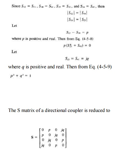
A directional coupler is a four-port waveguide junction as shown in Fig. 4-5-1. It consists of a primary waveguide 1-2 and a secondary waveguide 3-4.
When all ports are terminated in their characteristic impedances, there is free transmission of power, without reflection, between port 1 and port 2, and there is no transmission of power between port 1 and port 3 or between port 2 and port 4 because no coupling exists between these two pairs of ports.
The degree of coupling between port 1 and port 4 and between port 2 and port 3 depends on the structure of the coupler. The characteristics of a directional coupler can be expressed in terms of its coupling factor and its directivity.
Assuming that the wave is propagating from port 1 to port 2 in the primary line, the coupling factor and the directivity are defined,
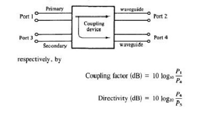
where P, = power input to port 1
P3 = power output from port 3
P4 = power output from port 4
It should be noted that port 2, port 3, and port 4 are terminated in their characteristic impedances. The coupling factor is a measure of the ratio of power levels in the primary and secondary lines. Hence if the coupling factor is known, a fraction of power measured at port 4 may be used to determine the power input at port
1. This significance is desirable for microwave power measurements because no disturbance, which may be caused by the power measurements, occurs in the primary line.
2. The directivity is a measure of how well the forward traveling wave in the primary waveguide couples only to a specific port of the secondary waveguide. An ideal directional coupler should have infinite directivity. In other words, the power at port 3 must be zero because port 2 and port 4 are perfectly matched.
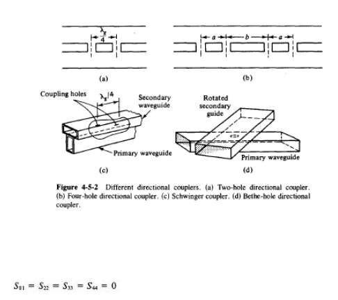
3. Actually, well-designed directional couplers have a directivity of only 30 to 35 dB. Several types of directional couplers exist, such as a two-hole directional couler, four-hole directional coupler, reverse-coupling directional coupler (Schwinger coupler), and Bethe-hole directional coupler (refer to Fig. 4-5-2). Only the very commonly used two-hole directional coupler is described here.
As noted, there is no coupling between port 1 and port 3 and between port 2 and port 4. Thus
14. TWO HOLE DIRECTIONAL COUPLERS:
Two-Hole Directional Couplers
A two-hole directional coupler with traveling waves propagating in it is illustrated in Fig. 4-5-3. The spacing between the centers of two holes must be
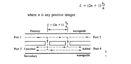
A fraction of the wave energy entered into port 1 passes through the holes and is radiated into the secondary guide as the holes act as slot antennas.
The forward waves in the secondary guide are in the same phase, regardless of the hole space, and are added at port 4.
The backward waves in the secondary guide (waves are progressing from right to left) are out of phase by (2L/ A8)27T rad and are canceled at port 3.
In a directional coupler all four ports are completely matched. Thus the diagonal elements of the S matrix are zeros
15. FERRITES:
An isolator is a nonreciprocal transmission device that is used to isolate one component from reflections of other components in the transmission line. An ideal isolator completely absorbs the power for propagation in one direction and provides lossless transmission in the opposite direction.
Thus the isolator is usually called uniline. Isolators are generally used to improve the frequency stability of microwave generators, such as klystrons and magnetrons, in which the reflection from the load affects the generating frequency.
In such cases, the isolator placed between the generator and load prevents the reflected power from the unmatched load from returning to the generator. As a result, the isolator maintains the frequency stability of the generator. Isolators can be constructed in many ways.
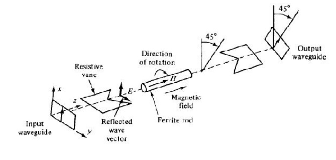
They can be made by terminating ports 3 and 4 of a four-port circulator with matched loads. On the other hand, isolators can be made by inserting a ferrite rod along the axis of a rectangular waveguide as shown in Fig. 4-6-5. The isolator here is a Faraday-rotation isolator. Its operating principle can be explained as follows [5]. The input resistive card is in the y-z plane, and the output resistive card is displaced 45° with respect to the input card.
The de magnetic field, which is applied longitudinally to the ferrite rod, rotates the wave plane of polarization by 45°. The degrees of rotation depend on the length and diameter of the rod and on the applied de magnetic field. An input TE10 dominant mode is incident to the left end of the isolator. Since the TE10 mode wave is perpendicular to the input resistive card, the wave passes through the ferrite rod without attenuation.
The wave in the ferrite rod section is rotated clockwise by 45° and is normal to the output resistive card. As a result of rotation, the wave arrives at the output
16. TERMINATION:
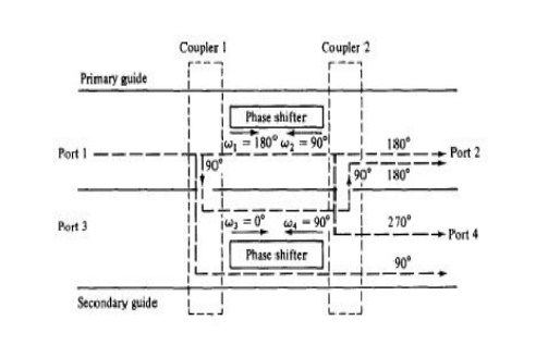
A microwave circulator is a multiport waveguide junction in which the wave can flow only from the nth port to the (n + l)th port in one direction
Although there is no restriction on the number of ports, the four-port microwave circulator is the most common. One type of four-port microwave circulator is a combination of two 3-dB side-hole directional couplers and a rectangular waveguide with two nonreciprocal phase shifters as shown in Fig
The operating principle of a typical microwave circulator can be analyzed with the aid of Fig. Each of the two 3-dB couplers in the circulator introduces a phase shift of 90°, and each of the two phase shifters produces a certain amount of phase change in a certain direction as indicated.
When a wave is incident to port 1, the wave is split into two components by coupler 1. The wave in the primary guide arrives at port 2 with a relative phase change of 180°. The second wave propagates through the two couplers and the secondary guide and arrives at port 2 with a relative phase shift of 180°. Since the two waves reaching port 2 are in phase, the power transmission is obtained from port 1 to port 2.
However, the wave propagates through the primary guide, phase shifter, and coupler 2 and arrives at port 4 with a phase change of 270°. The wave travels through coupler 1 and the secondary guide, and it arrives at port 4 with a phase shift of 90°. Since the two waves reaching port 4 are out of phase by 180°, the power transmission from port 1 to port 4 is zero. In general, the differential propagation constants in the two directions of propagation in a waveguide containing ferrite phase shifters should be
17. GYRATOR:
A gyrator is a passive, linear, lossless, two-port electrical network element proposed in 1948 by Bernard D. H. Tellegen as a hypothetical fifth linear element after the resistor, capacitor, inductor and ideal transformer. Unlike the four conventional elements, the gyrator is non-reciprocal. Gyrators permit network realizations of two-(or-more)-port devices which cannot be realized with just the conventional four elements.
In particular, gyrators make possible network realizations of isolators andcirculators. Gyrators do not however change the range of one-port devices that can be realized. Although the gyrator was conceived as a fifth linear element, its adoption makes both the ideal transformer and either the capacitor or inductor redundant. Thus the number of necessary linear elements is in fact reduced to three. Circuits that function as gyrators can be built with transistors and op amps using feedback.
ellegen invented a circuit symbol for the gyrator and suggested a number of ways in which a practical gyrator might be built.
An important property of a gyrator is that it inverts the current-voltage characteristicof an electrical component or network. In the case of linear elements, the impedanceis also inverted. In other words, a gyrator can make a capacitive circuit behaveinductively, a series LC circuit behave like a parallel LC circuit, and so on. It is primarily used in active filter design and miniaturization.
18. ISOLATOR CIRCULATOR:
An isolator is a nonreciprocal transmission device that is used to isolate one component from reflections of other components in the transmission line. An ideal isolator completely absorbs the power for propagation in one direction and provides lossless transmission in the opposite direction. Thus the isolator is usually called uniline.
Isolators are generally used to improve the frequency stability of microwave generators, such as klystrons and magnetrons, in which the reflection from the load affects the generating frequency. In such cases, the isolator placed between the generator and load prevents the reflected power from the unmatched load from returning to the generator.
As a result, the isolator maintains the frequency stability of the generator. Isolators can be constructed in many ways. They can be made by terminating ports 3 and 4 of a four-port circulator with matched loads. On the other hand, isolators can be made by inserting a ferrite rod along the axis of a rectangular waveguide as shown in Fig. 4-6-5.
The isolator here is a Faraday-rotation isolator. Its operating principle can be explained as follows [5]. The input resistive card is in the y-z plane, and the output resistive card is displaced 45° with respect to the input card. The de magnetic field, which is applied longitudinally to the ferrite rod, rotates the wave plane of polarization by 45°. The degrees of rotation depend on the length and diameter of the rod and on the applied de magnetic field. An input TE10 dominant mode is incident to the left end of the isolator. Since the TE10 mode wave is perpendicular to the input resistive card, the wave passes through the ferrite rod without attenuation.
The wave in the ferrite rod section is rotated clockwise by 45° and is normal to the output resistive card. As a result of rotation, the wave arrives at the output end without attenuation at all. On the contrary, a reflected wave from the output end is similarly rotated clockwise 45° by the ferrite rod.
However, since the reflected wave is parallel to the input resistive card, the wave is thereby absorbed by the input card. The typical performance of these isolators is about 1-dB insertion loss in forward transmission and about 20- to 30-dB isolation in reverse attenuation
19. ATTENUATOR:
A microwave circulator is a multiport waveguide junction in which the wave can flow only from the nth port to the (n + l)th port in one direction (see Fig. 4-6-2). Although there is no restriction on the number of ports, the four-port microwave circulator is the most common. One type of four-port microwave circulator is a combination of two 3-dB side-hole directional couplers and a rectangular waveguide with two nonreciprocal phase shifters as shown in Fig. 4-6-3.
The operating principle of a typical microwave circulator can be analyzed with the aid of Fig. 4-6-3. Each of the two 3-dB couplers in the circulator introduces a phase shift of 90°, and each of the two phase shifters produces a certain amount of phase change in a certain direction as indicated.
When a wave is incident to port 1, the wave is split into two components by coupler 1. The wave in the primary guide arrives at port 2 with a relative phase change of 180°. The second wave propagates through the two couplers and the secondary guide and arrives at port 2 with a relative phase shift of 180°.
Since the two waves reaching port 2 are in phase, the power transmission is obtained from port 1 to port 2. However, the wave propagates through the primary guide, phase shifter, and coupler 2 and arrives at port 4 with a phase change of 270°. The wave travels through coupler 1 and the secondary guide, and it arrives at port 4 with a phase shift of 90°. Since the two waves reaching port 4 are out of phase by 180°, the power transmission from port 1 to port 4 is zero.
In general, the differential propagation constants in the two directions of propagation in a waveguide containing ferrite phase shifters should be where m and n are any integers, including zeros. A similar analysis shows that a wave incident to port 2 emerges at port 3 and so on. As a result, the sequence of power flow is designated as 1 ~ 2 ~ 3 ~ 4 ~ 1. Many types of microwave circulators are in use today.
However, their principles of operation remain the same. Figure 4-6-4 shows a four-port circulator constructed of two magic tees and a phase shifter. The phase shifter produces a phase shift of 180°. The explanation of how this circulator works is left as an exercise for the reader.

20. PHASE CHANGER:
21. S MARIX FOR MICROWAVE COMPONENTS:
H palne tee:
22. CYLINDRICAL CAVITY RESONATORS:
In general, a cavity resonator is a metallic enclosure that confines the electromagnetic energy. The stored electric and magnetic energies inside the cavity determine its equivalent inductance and capacitance. The energy dissipated by the finite conductivity of the cavity walls determines its equivalent resistance.
In practice, the rectangular-cavity resonator, circular-cavity resonator, and reentrant-cavity resonator are commonly used in many microwave applications. Theoretically a given resonator has an infinite number of resonant modes, and each mode corresponds to a definite resonant frequency.
When the frequency of an impressed signal is equal to a resonant frequency, a maximum amplitude of the standing wave occurs, and the peak energies stored in the electric and magnetic fields are equal. The mode having the lowest resonant frequency is known as the dominant mode.
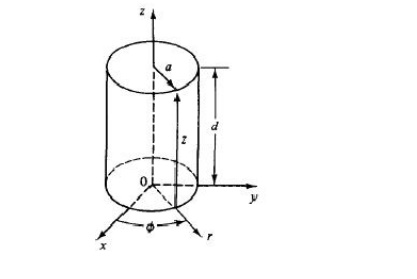
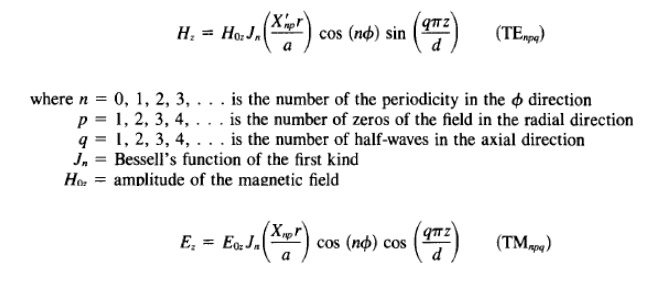
Circular-cavity resonator. A circular-cavity resonator is a circular waveguide with two ends closed by a metal wall (see Fig. 4-3-3). The wave function in the circular resonator should satisfy Maxwell's equations, subject to the same boundary conditions described for a rectangular-cavity resonator. It is merely necessary to choose the harmonic functions in z to satisfy the boundary conditions at the remaining two end walls. These can be achieved if
Related Topics