Chapter: Electronic Circuits : Frequency Analysis of BJT and MOSFET Amplifiers
Low frequency analysis of BJT
Low frequency analysis of BJT:
From
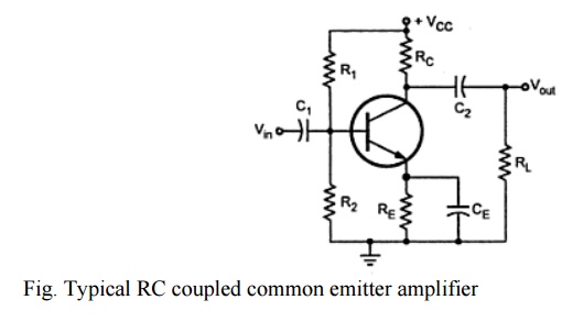
above figure, it has three RC networks that affect its gain as the frequency is
reduces below midrange. These are,
·
RC network formed by the input coupling capacitor C1
and input impedance of the amplifier.
·
RC network formed by the output coupling capacitor
C2, resistance looking in at the collector and load resistance.
·
RC network formed by the emitter bypass capacitor CE
and resistance looking in at the emitter.
Input RC network:
The
following figure shows the input RC network formed by C1 and the
input impedance of the amplifier.
The
resistance value is Rin = R1 || R2 || Rin(base)
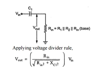
A
critical point in the amplifier response is generally accepted to occur when
the output voltage is 70.7 % of the input. At critical point,
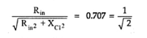
At this
condition, Rin = Xc1
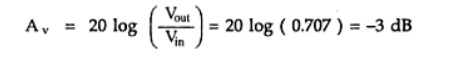
Overall
gain is reduced due to attenuation provided by the input RC network. The
reduction in overall gain is given by,
The
frequency fc at this condition is called lower critical frequency
and it is given by,
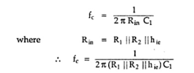
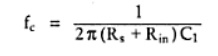
If the
resistance of input source is taken into account the above equation becomes,
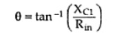
The phase
angle in an input RC circuit is expressed as
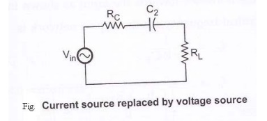
Output RC network:
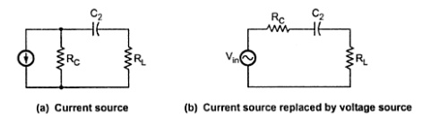
The above
figure shows the output RC network formed by C2, resistance looking
in at the collector and load resistance.
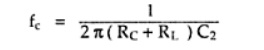
The
critical frequency for this RC network is given by,
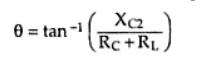
The phase
angle in output RC network is given as,
Bypass network:
From
above figure,
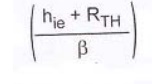
is the
resistance looking in at the emitter. It is derived as follows, R= (Vb
/ βIb) + hie / β
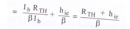
Where RTH
= R1 || R2 || Rs. It is the thevenin’s
equivalent resistance looking from the base of the transistor towards the
input.
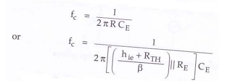
The
critical frequency for the bypass network is
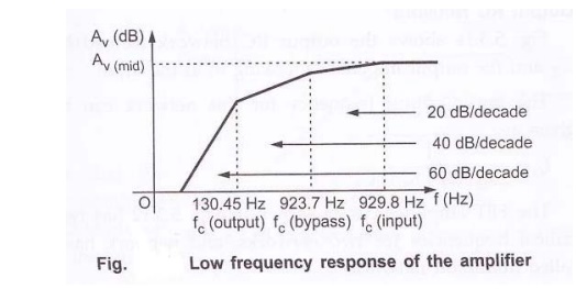
Problem:
Determine
the low frequency response of the amplifier circuit shown in the figure.
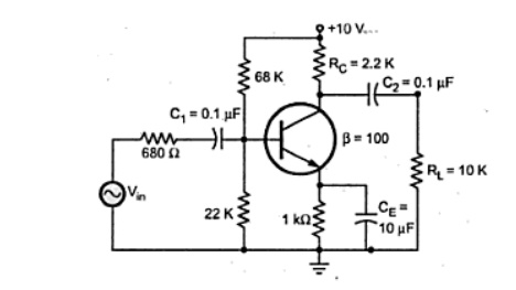
Solution:
It is
necessary to analyze each network to determine the critical frequency of the
amplifier.
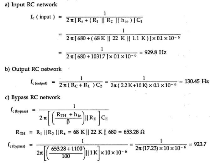
The above
analysis shows that the input network produces the dominant lower critical frequency.
Then the low frequency response of the given amplifier is shown in the
following figure.
Related Topics