Chapter: Fiber optics and Laser instruments : Industrial Applications of Laser
Laser for Measurement of Distance
Laser for Measurement of Distance:

Laser-based
distance measurements can be done using interferometricprinciples. Measurements
of length using optical interferometry have been performed since the 19th
century. But the limited intensity and coherence of conventional light sources
restricted the measurements, which were difficult and suitable for used only
over distances of a few centimeters. The development of lasers removed these
restrictions. Lasers have allowed interferometer to develop into a fast, highly
accurate and versatile technique for measuring longer distance.
Interferometric
measurement of distance can be highly accurate. It offers a higher degree of
precision than the pulsed time-of-flight or beam-modulation telemetry methods.
However, it is best suited to measurements made in a controlled atmosphere (for
example, indoors) over distances no greater than a few tens of meters.
Most
laser-based interferometric systems for measurement of distance use a frequency
stabilized helium-neon laser. An unstabilized laser, operating in a number of
longitudinal modes, will have a total linewidth around 109 Hz. This spread in
the frequency (or wavelength) will cause the interference fringes to become
blurred and to lose visibility as the distance increases. An unstabilized laser
is suitable for measurement only over distances of a few centimeters.
Stabilized lasers, usually in a temperature-controlled environment and
operating in a single longitudinal mode, are used for longer distances.
We
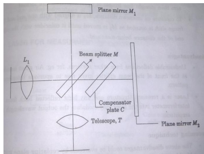
describe first the operation of a system based on the Michelson
interferometer,because it is easy to understand the basic principles of
interferometer distance measurement with reference to the Michelson
interferometer. Later we will describe variations that provide better stability
under conditions of atmospheric turbulence.
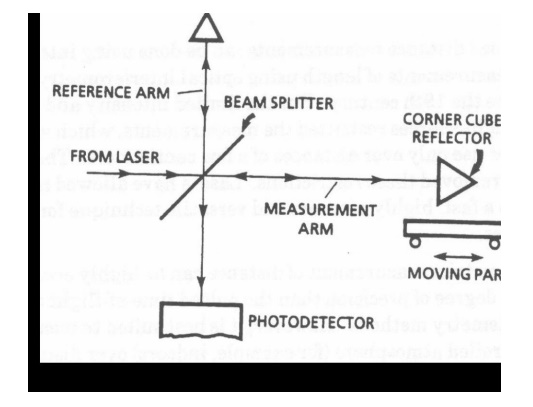
The beam
from the laser falls on a beam splitter that reflects half the beam in one
direction (the reference arm) and transmits the other half (the measurement
arm). The two beams are each reflected by mirrors, a stationary mirror in the
reference arm and a movable mirror in the measurement arm. In practice the
mirrors are often cube corner reflectors (retroreflectors) which offer better
stability against vibrations than conventional flat mirrors.
Schematic
diagram of the application of a Michelson interferometer to measurement of
distance The two reflected beams are recombined at the beam splitter to form an
interference pattern
that is
viewed by an observer or measured by a recorder such as a photo detector. The
character of the fringes is related to the different optical path lengths
traveled by the two beams before they are recombined.

Suppose,
for example, that the detector is viewing a bright fringe in the interference
pattern when the movable mirror is at a certain position. If the movable mirror
moves a distance equal to 1/4 of the wavelength of light, the round-trip
distance traversed by the light in the measurement arm will change by 1/2
wavelength, and the fringe pattern will change so that the detector now views a
dark fringe. The distance mesurement thus consists of counting the number of
fringe variations as the mirror moves. Each complete fringe corresponds to a
phase variation equal to 2p . The variation in phase d is determined by using
the equation
d = 4p D x/l
where l
is the wavelength of the light,
D x is the distance that the movable
mirror has moved.
It is
apparent that this method offers high precision, allowing measurements of D x to be made with an accuracy of the
order of a fraction of the wavelength of light.
(55)The maximum distance D x that can be measured in this way is given by: D x max = c/Dv
Where, c = velocity of light.
D v = linewidth (i.e., spread in
frequency) of the laser.
Related Topics