Chapter: Mechanical : Kinematics of Machinery : Kinematics of Cam Mechanisms Cams
Kinematics of Cam Mechanisms Cams
KINEMATICS OF CAM MECHANISMS CAMS
1 INTRODUCTION
A cam is
a mechanical device used to transmit motion to a follower by direct contact.
The driver is called the cam and the driven member is called the follower. In a
cam follower pair, the cam normally rotates while the follower may translate or
oscillate. A familiar example is the camshaft of an automobile engine, where
the cams drive the push rods (the followers) to open and close the valves in
synchronization with the motion of the pistons.
Types of cams
Cams can
be classified based on their physical shape.
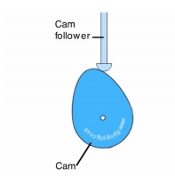
a) Disk or plate cam (Fig. 6.1a and b): The
disk (or plate) cam has an irregular contour to impart a specific motion to the follower. The follower moves in a
plane perpendicular to the axis of rotation of the camshaft and is held in
contact with the cam by springs or gravity.
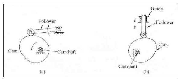
Fig. 6.1
Plate or disk cam.
b) Cylindrical cam (Fig. 6.2): The
cylindrical cam has a groove cut along its cylindrical surface. The roller follows the groove, and the follower moves in
a plane parallel to the axis of rotation of the cylinder.
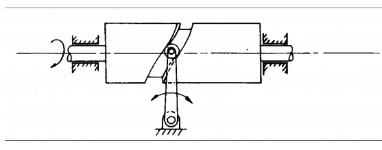
Fig. 6.2
Cylindrical cam.
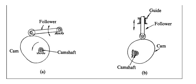
c) Translating cam (Fig. 6.3a and b). The
translating cam is a contoured or grooved plate sliding on a guiding surface(s). The follower may oscillate (Fig. 6.3a) or
reciprocate (Fig. 6.3b). The contour or the shape of the groove is determined
by the specified motion of the follower.
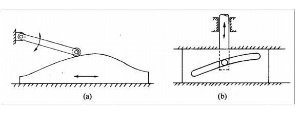
Fig. 6.3
Translating cam
Types of followers:
(i) Based on
surface in contact. (Fig.6.4)
(a) Knife
edge follower
(b) Roller
follower
(c)Flat
faced follower
(d) Spherical
follower
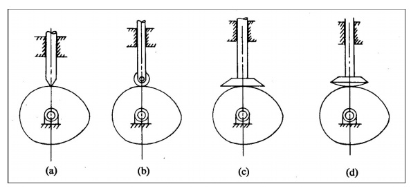
Fig. 6.4 Types of followers
(ii)Based on
type of motion: (Fig.6.5)
(a) Oscillating
follower
(b) Translating
follower
(iii)
Based on line of motion:
(a) Radial
follower: The lines of movement of in-line cam followers pass through the
centers of the camshafts (Fig. 6.4a, b, c, and d).
(b) Off-set
follower: For this type, the lines of movement are offset from the centers of
the camshafts (Fig. 6.6a, b, c, and d).
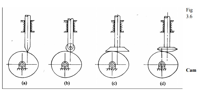
Fig.6.6
Off set followers
Cam nomenclature (Fig. 6.7):
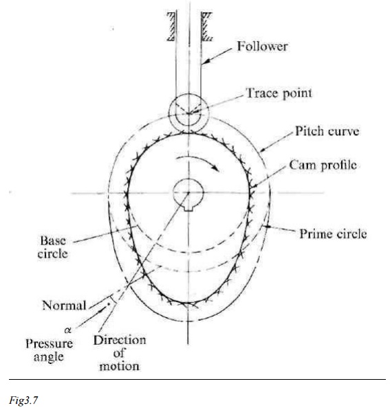
Cam Profile The contour of the working
surface of the cam.
Tracer
Point The point at the knife edge of a follower, or the center of a roller, or
the center of a spherical face.
Pitch Curve The path
of the tracer point.
Base Circle The smallest circle drawn,
tangential to the cam profile, with its center on the axis of the camshaft. The size of the base circle determines the size
of the cam.
Prime Circle The
smallest circle drawn, tangential to the pitch curve, with its center on the
axis of the camshaft.
Pressure Angle The angle between the normal to
the pitch curve and the direction of motion of the follower at the point of contact.
2 Types of follower motion:
Cam
follower systems are designed to achieve a desired oscillatory motion.
Appropriate displacement patterns are to be selected for this purpose, before
designing the cam surface. The cam is assumed to rotate at a constant speed and
the follower raises, dwells, returns to its original position and dwells again
through specified angles of rotation of the cam, during each revolution of the
cam. Some of the standard follower motions are as follows:
They are,
follower motion with,
(c) Uniform
velocity
(b) Modified
uniform velocity
(c) Uniform
acceleration and deceleration
(d) Simple
harmonic motion
(e) Cycloidal
motion
3 Displacement diagrams:
Displacement diagrams: In a cam
follower system, the motion of the follower is very important. Its displacement can be plotted against the angular
displacement θ of the cam and it is called as the displacement diagram. The
displacement of the follower is plotted along the y-axis and angular
displacement θ of the cam is plotted along x-axis. From the displacement
diagram, velocity and acceleration of the follower can also be plotted for
different angular displacements θ of the cam. The displacement, velocity and
acceleration diagrams are plotted for one cycle of operation i.e., one rotation
of the cam. Displacement diagrams are basic requirements for the construction
of cam profiles. Construction of displacement diagrams and calculation of
velocities and accelerations of followers with different types of motions are
discussed in the following sections.
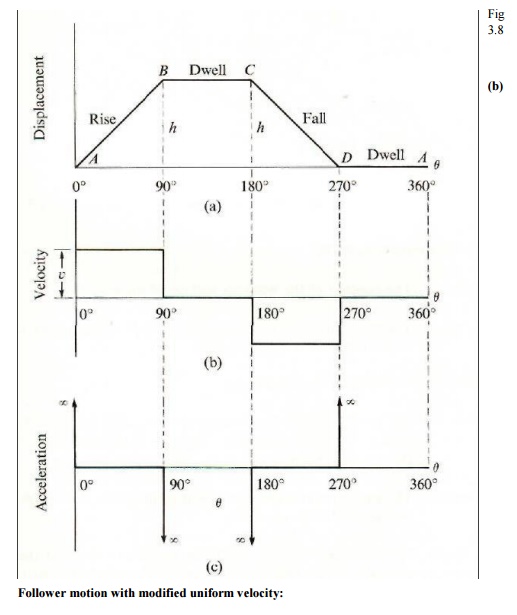
(a) Follower motion with Uniform velocity:
Fig.3.8
shows the displacement, velocity and acceleration patterns of a follower having
uniform velocity type of motion. Since the follower moves with constant
velocity, during rise and fall, the displacement varies linearly with θ. Also,
since the velocity changes from zero to a finite value, within no time,
theoretically, the acceleration becomes infinite at the beginning and end of
rise and fall.
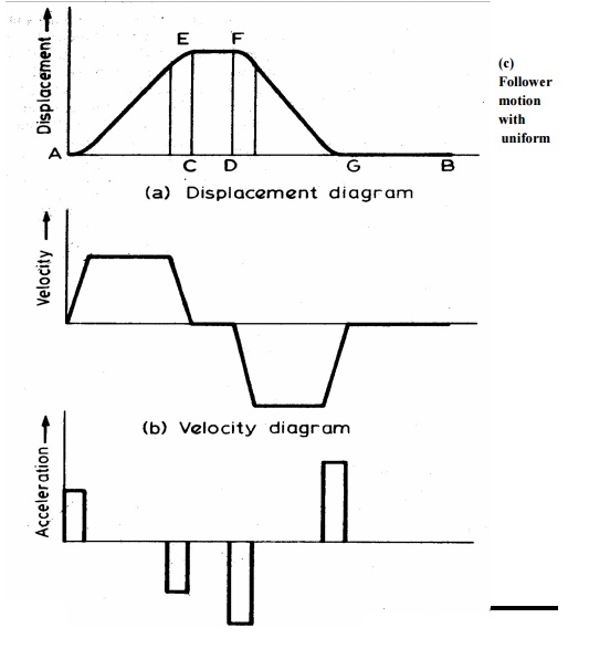
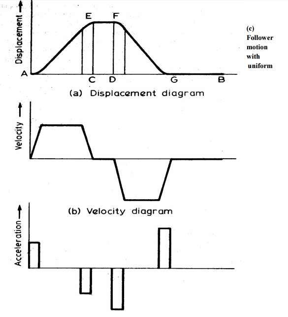
It is
observed in the displacement diagrams of the follower with uniform velocity
that the acceleration of the follower becomes infinite at the beginning and
ending of rise and return strokes. In order to prevent this, the displacement
diagrams are slightly modified.In the modified form, the velocity of the
follower changes uniformly during the beginning and end of each stroke.
Accordingly, the displacement of the follower varies parabolic ally during
these periods. With this modification, the acceleration becomes constant during
these periods, instead of being infinite as in the uniform velocity type of
motion. The displacement, velocity and acceleration patterns shown in fig 3.9
acceleration and retardation (UARM):
Here, the
displacement of the follower varies parabolically with respect to angular
displacement of cam. Accordingly, the velocity of the follower varies uniformly
with respect to angular displacement of cam. The acceleration/retardation of
the follower becomes constant accordingly. The displacement, velocity and
acceleration patterns are shown fig 3.10
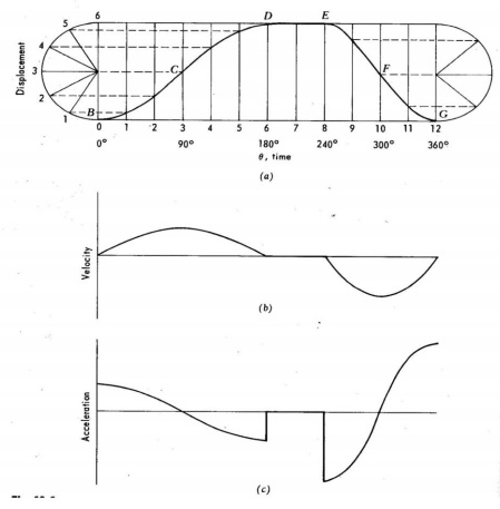
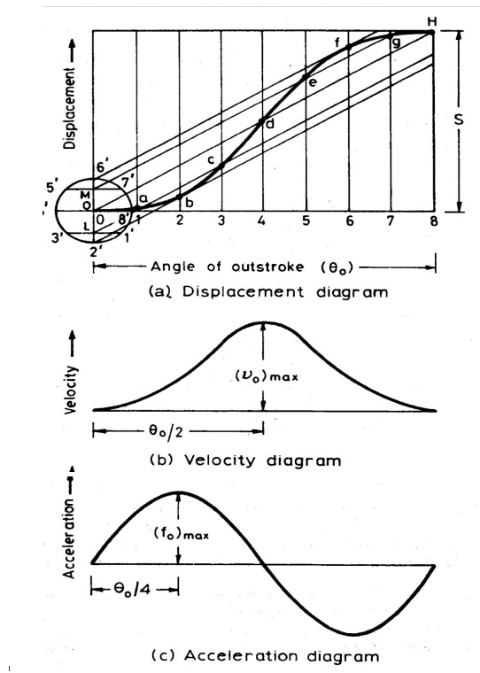
(d) Simple Harmonic Motion: In
fig3.11, the motion executed by point Pl, which is the projection of point P on the vertical diameter is called simple
harmonic motion. Here, P moves with uniform angular velocity ωp, along a circle
of radius r (r = s/2).
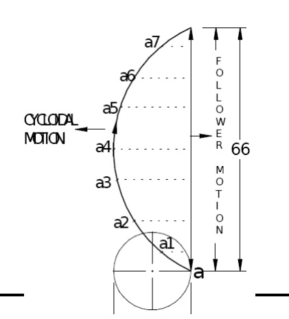
Cycloidal motion:
Cycloid
is the path generated by a point on the circumference of a circle, as the
circle rolls without slipping, on a straight/flat surface. The motion executed
by the follower here, is similar to that of the projection of a point moving
along a cyloidal curve on a vertical line as shown in figure 6.12.
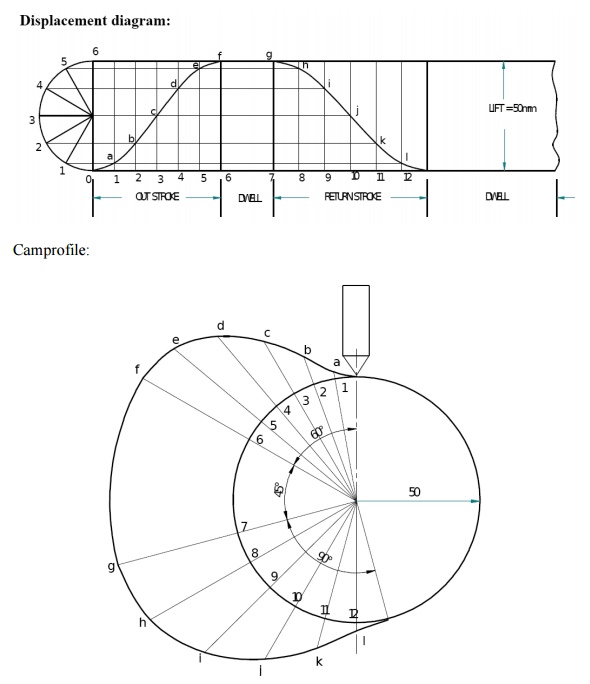
(1) Draw the cam profile for following conditions:
Follower
type = Knife edged, in-line; lift = 50mm; base circle radius = 50mm; out stroke
with SHM, for 600 cam rotation; dwell for 450cam
rotation; return stroke with SHM, for 90ocam rotation; dwell for the
remaining period.
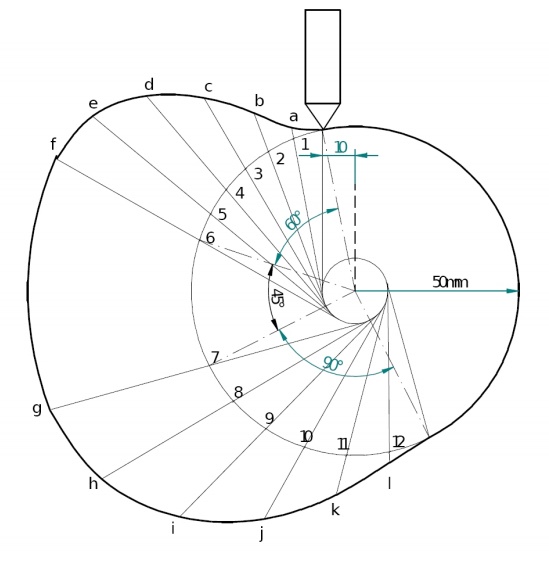
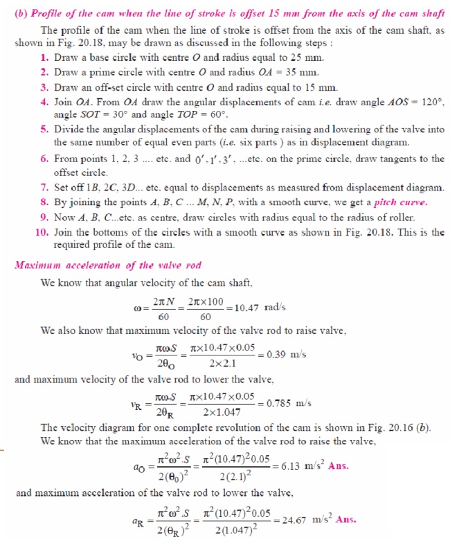
(2) Draw
the cam profile for the same operating conditions of with the follower off set
by 10 mm to the left of cam center.
Cam profile
with 10 mm offset:
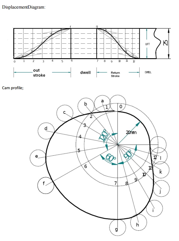
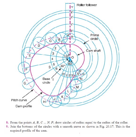
(2) Draw the cam profile for following conditions:
Follower
type = roller follower, in-line; lift = 25mm; base circle radius = 20mm; roller
radius = 5mm; out stroke with Uniform acceleration and retardation, for 1200
cam rotation; dwell for 600 cam rotation; return stroke with Uniform
acceleration and retardation , for 900 cam rotation; dwell for the
remaining period.
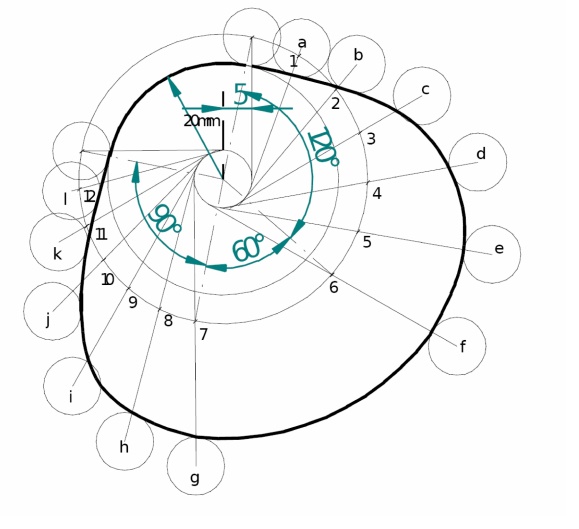
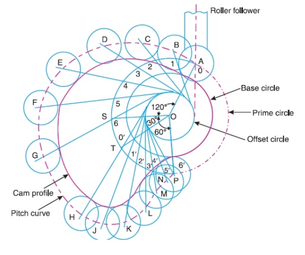
(4) Draw
the cam profile for conditions same with follower off set to right of cam
center by 5mm and cam rotating counter clockwise.
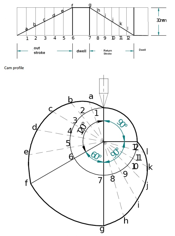
(3) Draw the cam profile for following conditions:
Follower
type = knife edged follower, in line; lift = 30mm; base circle radius =
20mm;out stroke with uniform velocity in 1200 of cam rotation; dwell
for 600; return stroke with uniform velocity, during 900
of cam rotation; dwell for the remaining period.
Displacement
Diagram
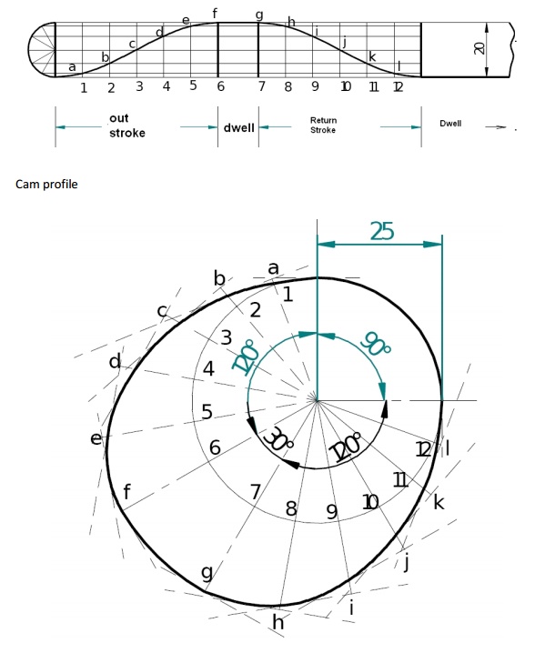
(4) Draw the cam profile for following conditions:
Follower
type = flat faced follower, in line; follower rises by 20mm with SHM in 1200of
cam rotation, dwells for 300 of cam rotation; returns with SHM in
1200 of cam rotation and dwells during the remaining period. Base
circle radius = 25mm.
Displacement
Diagram:
5 Layout of plate cam profiles:
·
Drawing the displacement diagrams for the different
kinds of the motions and the plate cam profiles for these different motions and
different followers.
·
SHM, Uniform velocity, Uniform acceleration and
retardation and Cycloidal motions
·
Knife-edge, Roller, Flat-faced and Mushroom
followers.
6Derivatives of Follower motion:
·
Velocity and acceleration of the followers for
various types of motions.
·
Calculation of Velocity and acceleration of the
followers for various types of motions.
7Circular arc and Tangent cam s:
·
Circular arc
·
Tangent cam
Standard cam motion:
·
Simple Harmonic Motion
·
Uniform velocity motion
·
Uniform acceleration and retardation motion
·
Cycloidal motion
8Pressure angle and undercutting:
·
Pressure angle
·
Undercutting
Related Topics