Chapter: Transmission Lines and Waveguides : Impedance Matching in High Frequency Lines
Impedance Matching By Stubs, Single Stub and Double Stub Matching
IMPEDANCE MATCHING BY STUBS, SINGLE STUB AND DOUBLE STUB MATCHING.
In microwave and radio-frequency engineering, a stub is a length of transmission line or waveguide that is connected at one end only. The free end of the stub is either left open-circuit or (especially in the case of waveguides) short-circuited. Neglecting transmission line losses, the input impedance of the stub is purely reactive; either capacitive or inductive, depending on the electrical length of the stub, and on whether it is open or short circuit. Stubs may thus be considered to be frequency-dependent capacitors and frequency-dependent inductors.
Because stubs take on reactive properties as a function of their electrical length, stubs are most common in UHF or microwave circuits where the line lengths are more manageable. Stubs are commonly used in antenna impedance matching circuits and frequency selective filters.
Smith charts can also be used to determine what length line to use to obtain a desired reactance.
Short circuited stub
The input impedance of a lossless short circuited line is,

where j is the imaginary unit, Z0 is the characteristic impedance of the line, β is the phase constant of the line, and l is the physical length of the line.
Thus, depending on whether tan(βl) is positive or negative, the stub will be inductive or capacitive, respectively.
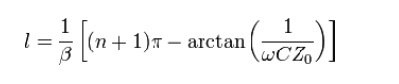
The Length of a stub to act as a capacitor C at an angular frequency of ω is then given by:
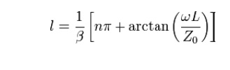
The length of a stub to act as an inductor L at the same frequency is given by:
Open circuited stub
The input impedance of a lossless open circuit stub is given by
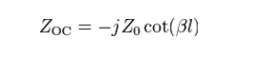
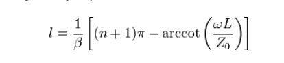
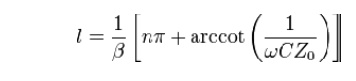
It follows that whether cot(βl) is positive or negative, the stub will be capacitive or inductive, respectively. The length of an open circuit stub to act as an Inductor L at an angular frequency of ω is:
The length of an open circuit stub to act as a capacitor C at the same frequency is:
Stub matching
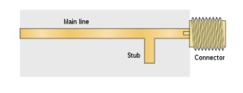
In a strip line circuit, a stub may be placed just before an output connector to compensate for small mismatches due to the device's output load or the connector itself.
Stubs can be used to match a load impedance to the transmission line characteristic impedance. The stub is positioned a distance from the load. This distance is chosen so that at that point the resistive part of the load impedance is made equal to the resistive part of the characteristic impedance by impedance transformer action of the length of the main line. The length of the stub is chosen so that it exactly cancels the reactive part of the presented impedance. That is, the stub is made capacitive or inductive according to whether the main line is presenting an inductive or capacitive impedance respectively. This is not the same as the actual impedance of the load since the reactive part of the load impedance will be subject to impedance transformer action as well as the resistive part.
In the method of impendence matching using stub, an open or closed stub line of suitable length is used as a reactance shunted across the transmission line at a designated distance from the load ,to tune the length of the line and the load to resonance with an anti resonant resistance equal to Ro. Matching stubs can be made adjustable so that matching can be corrected on test.
Single stub will only achieve a perfect match at one specific frequency. For wideband matching several stubs may be used spaced along the main transmission line. The resulting structure is filter-like and filter design techniques are applied. For instance, the matching network may be designed as a Chebyshev filter but is optimised for impedance matching instead of passband transmission. The resulting transmission function of the network has a passband ripple like the Chebyshev filter, but the ripples never reach 0dB insertion loss at any point in the passband, as they would do for the standard filter.
Single stub impedance matching:
• The load should be matched to the characteristic impedance of the line so that as much power as possible is transmitted from the generator to the load for radio-frequency power transmission.
• The lines should be matched because reflections from mismatched loads and junctions will result in echoes and will distort the information-carrying signal for information transmission.
• Short-circuited (instead of open-circuited) stubs are used for impedance-matching on transmission lines.
• Single-stub method for impedance matching : an arbitrary load impedance can be matched to a transmission line by placing a single short-circuited stub in parallel with the line at a suitable location
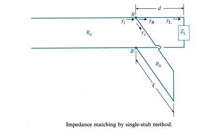
the input admittance at BB’ looking toward the load without the stub.
• Our impedance- (or admittance-) matching problem : to determine the location d and the length of the stub such that
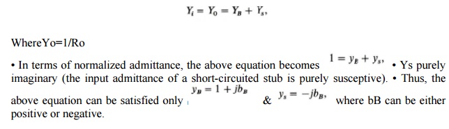
Objectives : (1) to find the length d such that the admittance YB of the load section looking to the right of terminal BB’ has a unitary real part, and (2) to find the length of the stub required to cancel the imaginary part.
A short circuited stub is preferred to an open circuited stub because of greater ease in constructions and because of the inability to maintain high enough insulation resistance at the open –circuit point to ensure that the stub is really open circuited .A shorted stub also has a lower loss of energy due to radiation ,since the short – circuit can be definitely established with a large metal plate ,effectively stopping all field propagation.
Double stub matching:s
Another possible method of impedance matching is to use two stubs in which the locations of the stub are arbitrary, the two stub lengths furnishing the required adjustments. The spacing is frequently made l/4.This is called double stub matching.
Double stub matching is preferred over single stub due to following disadvantages of single stub.
1. Single stub matching is useful for a fixed frequency .So as frequency changes the location of single stub will have to be changed.
2. The single stub matching system is based on the measurement of voltage minimum .Hence for coxial line it is very difficult to get such voltage minimum, without using slotted line section.
Related Topics