Chapter: Civil : Highway Planning and Alignment : Highway Engineering
Highway Planning And Alignment
History of highway engineering
The history of highway enginnering gives us an idea about the roads of ancient times. Roads in Rome were constructed in a large scale and it radiated in many directions helping them in military operations. Thus they are considered to be pioneers in road construction. In this section we will see in detail about Ancient roads, Roman roads, British roads, French roads etc.
1 Ancient Roads
The first mode of transport was by foot. These human pathways would have been developed for specific purposes leading to camp sites, food, streams for drinking water etc. The next major mode of transport was the use of animals for transporting both men and materials. Since these loaded animals required more horizontal and vertical clearances than the walking man, track ways emerged. The invention of wheel in Mesopotamian civilization led to the development of animal drawn vehicles. Then it became necessary that the road surface should be capable of carrying greater loads. Thus roads with harder surfaces emerged. To provide adequate strength to carry the wheels, the new ways tended to follow the sunny drier side of a path. These have led to the development of foot-paths. After the invention of wheel, animal drawn vehicles were
developed and the need for hard surface road emerged. Traces of such hard roads were obtained from various ancient civilization dated as old as 3500 BC. The earliest authentic record of road was found from Assyrian empire constructed about 1900 BC.
2 Roman roads
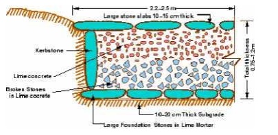
The earliest large scale road construction is attributed to Romans who constructed an extensive system of roads radiating in many directions from Rome. They were a remarkable achievement and provided travel times across Europe, Asia minor, and north Africa. Romans recognized that the fundamentals of good road construction were to provide good drainage, good material and good workmanship. Their roads were very durable, and some are still existing. Roman roads were always constructed on a firm
formed subgrade strengthened where necessary with wooden piles. The roads were bordered on both sides by longitudinal drains. The next step was the construction of the agger. This was a raised formation up to a 1 meter high and 15 m wide and was constructed with materials excavated during the side drain construction. This was then topped with a sand leveling course. The agger contributed greatly to moisture control in the pavement. The pavement structure on the top of the agger varied greatly. In the case of heavy traffic, a surface course of large 250 mm thick hexagonal flag stones were provided. A typical cross section of roman road The main features of the Roman roads are that they were built straight regardless of gradient and used heavy foundation stones at the bottom. They mixed lime and volcanic puzzolana to make mortar and they added gravel to this mortar to make concrete. Thus concrete was a major Roman road making innovation.
3 French roads
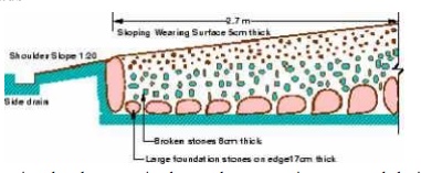
The next major development in the road construction occurred during the regime of Napoleon. The significant contributions were given by Tresaguet in 1764 and a typical cross section of this road. He developed a cheaper method of construction than the lavish and locally unsuccessful revival of Roman practice. The pavement used 200 mm pieces of quarried stone of a more compact form and shaped such that they had at least one flat side which was placed on a compact formation.
Smaller pieces of broken stones were then compacted into the spaces between larger stones to provide a level surface. Finally the running layer was made with a layer of 25 mm sized broken stone. All this structure was placed in a trench in order to keep the running surface level with the surrounding country side. This created major drainage problems which were counteracted by making the surface as impervious as possible, cambering the surface and providing deep side ditches.
He gave much importance for drainage. He also enunciated the necessity for continuous organized maintenance, instead of intermittent repairs if the roads were to be kept usable all times. For this he divided the roads between villages into sections of such length that an entire road could be covered by maintenance men living nearby.
4 British roads
The British government also gave importance to road construction. The British engineer John Macadam introduced what can be considered as the first scientific road construction method. Stone size was an important element of Macadam recipe. By empirical observation of many roads.
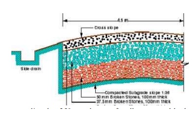
he came to realize that 250 mm layers of well compacted broken angular stone would provide the same strength and stiffness and a better running surface than an expensive pavement founded on large stone blocks. Thus he introduced an economical method of road construction.
The mechanical interlock between the individual stone pieces provided strength and stiffness to the course. But the inter particle friction abraded the sharp interlocking faces and partly destroy the effectiveness of the course. This effect was overcome by introducing good quality interstitial finer material to produce a well-graded mix. Such mixes also proved less permeable and easier to compact.
Bombay road congress:
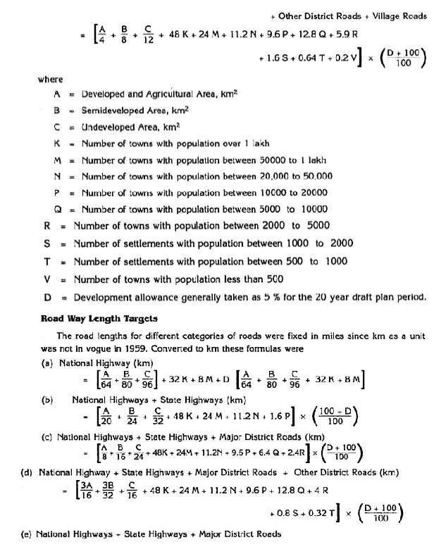
The length of roads envisaged under the Nagpur plan was
achieved by the end of it, but the road system was deficient in many respects.
The changed economic, industrial and agricultural conditions in the country
warranted a review of the Nagpur plan. Accordingly a 20-year plan was drafted
by the Roads wing of Government of India, which is popularly known as the
Bombay plan. The highlights of the plan were:
·
It was the second 20 year road plan (1961-1981)
·
The total road length targeted to construct was
about 10 lakhs.
·
Rural roads were given specific attention.
Scientific methods of construction was proposed for the rural roads. The
necessary technical advice to the Panchayaths should be given by State PWD's.
·
They suggested that the length of the road should
be increased so as to give a road density of 32kms/100 sq.km
The
construction of 1600 km of expressways was also then included in the plan.

1.7
Camber
Camber or cant is the cross slope provided to
raise middle of the road surface in the transverse direction to drain of rain
water from road surface. The objectives of providing camber are:
_ Surface protection especially for gravel and bituminous
roads _ Sub-grade protection by proper drainage
_ Quick
drying of pavement which in turn increases safety
Too steep slope is undesirable for it will erode the surface.
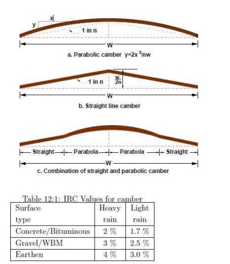
Camber is measured in 1 in n or n% (Eg. 1 in 50 or 2%) and the value depends on
the type of pavement surface. The values suggested by IRC for various
categories of pavement is given in Table .
1.7.1
Types of cambers.
The
common types of camber are parabolic, straight, or combination of them
1.8 Width
of carriage way
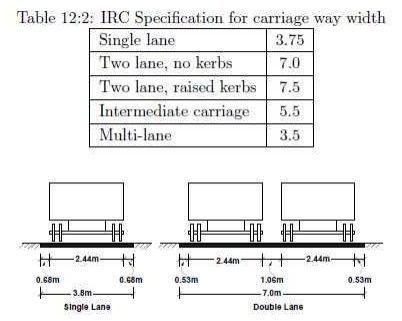
Width of the carriage way or the width of the pavement depends
on the width of the traffic lane and number of lanes. Width of a traffic lane
depends on the width of the vehicle and the clearance. Side clearance improves
operating speed and safety. The maximum permissible width of a vehicle is 2.44
and the desirable side clearance for single lane traffic is 0.68 m. This
require minimum of lane width of 3.75 m for a single lane road .However, the
side clearance required is about 0.53 m, on either side and 1.06 m in the
center. Therefore, a two lane road require minimum of 3.5 meter for each lane
The desirable carriage way width recommended by IRC is given in Table
1.9
Importance of Kerbs
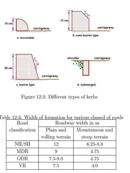
Kerbs indicate the boundary between the carriage
way and the shoulder or islands or
footpaths.
Different
types of kerbs are
Low or mountable kerbs : This type of kerbs are
provided such that they encourage the traffic to remain in the through traffic
lanes and also allow the driver to enter the shoulder area with little
difficulty. The height of this kerb is about 10 cm above the pavement edge with
a slope which allows the vehicle to climb easily. This is usually provided at
medians and channelization schemes and also helps in longitudinal drainage.
Semi-barrier type kerbs : When the pedestrian
traffic is high, these kerbs are provided. Their height is 15 cm above the
pavement edge. This type of kerb prevents encroachment of parking vehicles, but
at acute emergency it is possible to drive over this kerb with some difficulty.
Barrier type kerbs : They
are designed to discourage vehicles from leaving the pavement. They are
provided when there is considerable amount of pedestrian traffic. They are
placed at a height of 20 cm above the pavement edge with a steep batter.
Submerged kerbs: They are used in rural
roads. The kerbs are provided at pavement edges between the pavement
edge and shoulders. They provide lateral confinement and stability to the
pavement.
Width of
formation:
Width of
formation or roadway width is the sum of the widths of pavements or carriage
way including separators and shoulders.
1.10
Right of way.
Right of way (ROW) or land width is the width of
land acquired for the road, along its alignment. It should be adequate to
accommodate all the cross-sectional elements of the highway and may reasonably
provide for future development. To prevent ribbon development along highways,
control lines and building lines may be provided. Control line is a line which
represents the nearest limits of future uncontrolled building activity in
relation to a road. Building line represents a line on either side of the road,
between which and the road no building activity is permitted at all. The right
of way width is governed by:
Width of formation: It
depends on the category of the highway and width of roadway and road margins.
Height of embankment or depth of cutting: It is
governed by the topography and the vertical alignment.
Side slopes of embankment or cutting: It
depends on the height of the slope, soil type etc. Drainage system and
their size which depends on rainfall, topography etc.
Sight
distance considerations : On curves etc. there is restriction to the visibility
on the inner side of the curve due to the presence of some obstructions like
building structures etc.
Reserve
land for future widening: Some land has to be acquired in advance anticipating
future developments like widening of the road.
The importance of reserved land is emphasized by the
following. Extra width of land is available for the construction of roadside
facilities. Land acquisition is not possible later, because the land may be
occupied for various other purposes (buildings, business etc.)
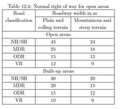
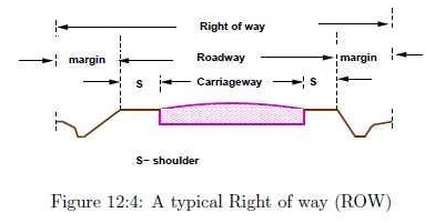
The
normal ROW requirements for built up and open areas as specified by IRC is
given in Table 12:4 A typical cross section of a ROW is given in Figure 12:4.
1.11
Alignment
The
position or the layout of the central line of the highway on the ground is
called the alignment. Horizontal alignment includes straight and curved paths.
Vertical alignment includes level and gradients. Alignment decision is
important because a bad alignment will enhance the construction, maintenance
and vehicle operating costs. Once an alignment is fixed and constructed, it is
not easy to change it due to increase in cost of adjoining land and
construction of costly structures by the roadside.
Requirements
The
requirements of an ideal alignment are
The alignment between two terminal stations should be short
and as far as possible be straight, but due to some practical considerations
deviations may be needed.
The alignment should be easy to construct and
maintain. It should be easy for the operation of vehicles. So to the maximum
extend easy gradients and curves should be provided.
It should be safe both from the construction and operating
point of view especially at slopes, embankments, and cutting. It should have
safe geometric features.
The alignment should be economical and it can be considered so
only when the initial cost, maintenance cost, and operating cost are minimum.
Factors
controlling alignment
We have seen the requirements of an alignment. But it is not
always possible to satisfy all these requirements. Hence we have to make a
judicial choice considering all the factors.
The
various factors that control the alignment are as follows:
1.Obligatory points: These are the control points
governing the highway alignment. These points are classified into two
categories. Points through which it should
pass and
points through which it should not pass. Some of the examples are:
o Bridge
site: The bridge can be located only where the river has straight and permanent
path and also where the abutment and pier can be strongly founded. The road
approach to the bridge should not be curved and skew crossing should be avoided
as possible. Thus to locate a bridge the highway alignment may be changed.
o Mountain:
While the alignment passes through a mountain, the various alternatives are to
either construct a tunnel or to go round the hills. The suitability
of the alternative depends on factors like topography, site
conditions and construction and operation cost.
o Intermediate
town: The alignment may be slightly deviated to connect an intermediate town or
village nearby.
These were some of the obligatory points through which the
alignment should pass. Coming to the second category, that is the points
through which the alignment should not pass are:
Religious places: These have been protected by the law from
being acquired for any purpose. Therefore, these points should be avoided while
aligning.
Very
costly structures: Acquiring such structures means heavy compensation
which would result in an increase in initial cost. So the
alignment may be deviated not to pass through that point.
Lakes/ponds etc: The presence of a lake or pond on the
alignment path would also necessitate deviation of the alignment.
2. Traffic: The alignment should suit the traffic
requirements. Based on the origin- destination data of the area, the desire
lines should be drawn. The new alignment should be drawn keeping in view the
desire lines, traffic flow pattern etc.
3. Geometric
design: Geometric design factors such as gradient, radius of curve, sight
distance etc. also govern the alignment of the highway. To keep the radius of
curve minimum, it may be required to change the alignment. The alignments
should be finalized such that the obstructions to visibility do not restrict
the minimum requirements of sight distance. The design standards vary with the
class of road and the terrain and accordingly the highway should be aligned.
Economy:
The alignment finalized should be economical. All the three costs i.e.
construction, maintenance, and operating cost should be minimum. The
construction cost can be decreased much if it is possible to maintain a balance
between cutting and filling. Also try to avoid very high embankments and very
deep cuttings as the construction cost will be very higher in these cases.
Related Topics