Chapter: Civil : Railway Airport Harbour Engineering : Railway Engineering : Subgrade and Formation
Failure of Railway Embankment
Failure of
Railway Embankment
A railway
embankment may fail due to the following causes.
(a) Failure
of the natural ground
(b) Failure
of the fill material in the embankment
(c) Failure
of the formation top
Whatever
may be the cause of failure, the normal symptoms are the following.
(a) Variation
in cross levels
(b) Loss of
ballast
(c) Upheaval
of the ground beyond the toes of the embankment
(d) Slips in
bank slopes
These
failures are discussed in the subsequent sections.
1 Failure of Natural Ground
The natural ground on which the
embankment is made can fail either due to shear failure or due to excessive
settlement. Failure of this kind is generally associated with the upheaval of
the ground beyond the toes of the embankment. Shear failure of natural ground
generally takes place when construction is in progress or immediately after
construction. Once the ground stabilizes, it hardly fails under existing
embankments.
The following remedial measures
are generally adopted to improve the load-carrying capacity of natural ground
and hasten the process of settlement.
(a) Provision
of suitably spaced sheet or ordinary piles on either side of the embankment,
which will check shear failure by obstructing the slipping mass.
(b) Provision
of a balancing embankment to increase the load on the natural ground to check
its heaving tendency.
(c) Provision
of sand drains to help quicker consolidation.
2 Failure of the Fill Material of
Embankments
Sometimes shear failure and
excessive settlement of an embankment takes place due to the failure of the
fill material of the embankment. This can easily be avoided by judicious
selection of the fill material, better construction procedures, and adopting a
suitably designed section for a new embankment. The main reasons for this type
of failure are the following.
(a) Heavy
traffic causing excessive stress in the soil, beyond its safe limit
(b) Inadequate
side slopes of the bank
(c) Percolation
of water in the embankment, thereby increasing the weight of the soil on one
hand and reducing its bearing capacity and shear resistance on the other. Shear
failure of existing embankments is quite common and occurs due to slips. Other
causes of failure are the weights of the embankment and the moving loads on it.
The forces resisting the failure are the cohesion
and
internal friction of the fill material.
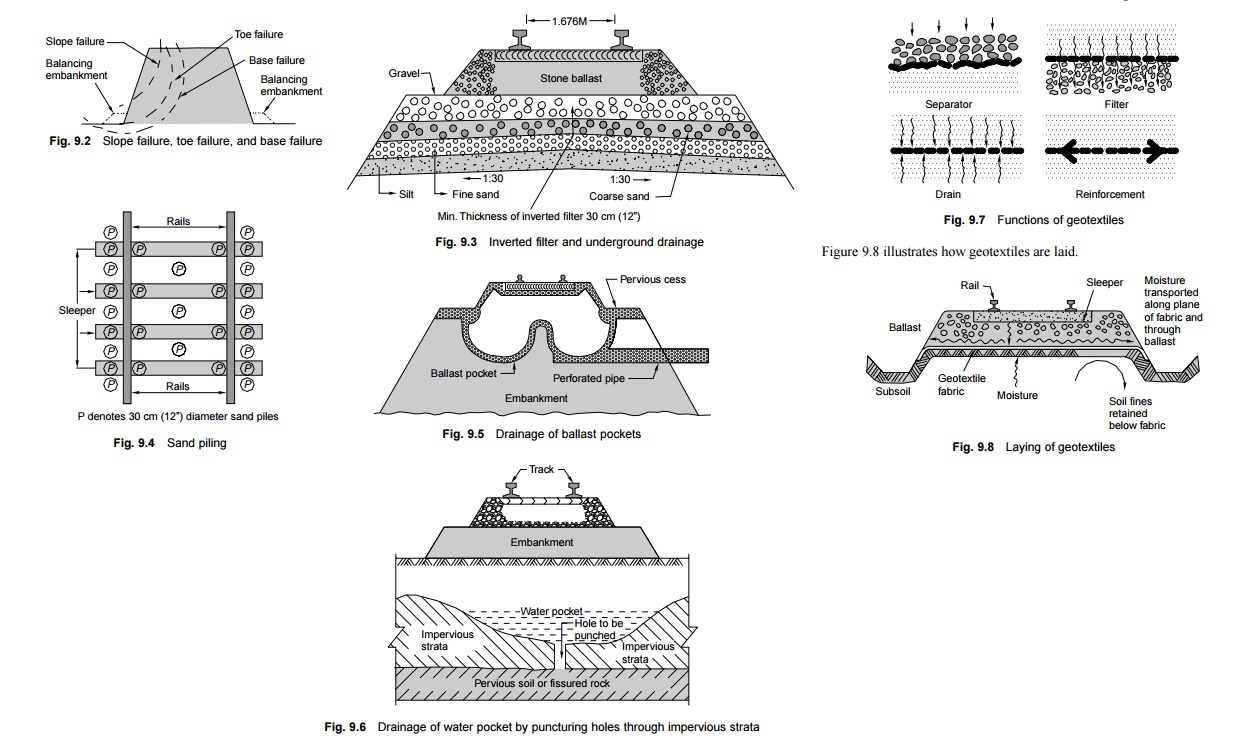
The following types of slip
failures may occur along different planes, as shown in Fig. 9.2.
l A slip
passing through the toe of the bank known as toe failure.
l A slip
passing below the toe of the bank through its base known as base failure.
l A slip
passing above the toe of the bank through its slope known as slope failure.
The
remedies effective for such failures are listed below.
(a) Providing
vertical piles on the slope on either side of the track, spaced at suitable
intervals. These piles, which may be of scrap rail, bullies, etc., help check
shear failure by causing an obstruction for the slip mass. This method was
adopted on Ganga Bridge, Mokameh, and was found to be quite successful.
(b) Providing
balancing embankments on either side of the embankment as shown in Fig. 9.2.
(c) Flattening
the side slopes.
(d) Reducing
the height of the embankment.
(e) Providing
a lighter material at the top of the embankment, replacing the older material.
(f) Providing
proper surface and sub-surface drainage.
3 Failure of Formation Top
Failure of the formation top is
very common in clayey soils during or just after monsoons. Some locations may
trouble throughout the year. The main causes for such failures are the
following.
Low bearing capacity of the soil Sinking
of the ballast and the track, and the heaving up of cesses and bulging
of side slopes as a consequence. The ballast punches into the formation causing
ballast pockets.
Action of water and moving loads The top
soil becomes soft and gets pumped up resulting in the sinking of the
ballast. The ballast also gets clogged and looses its drainage property.
Effect of weather Cracks
develop on the formation during the summer months and the ballast sinks
through the cracks, resulting in the settlement of the track. The situation
gets further worsened during the monsoons when water seeps through these
cracks, turning the upper layers of the formation to slush and resulting in the
formation of deeper ballast pockets.
The impact of moving loads and
the development of hydrostatic pressure further deepens the ballast on the side
slopes as well and can lead to slips in extreme cases. These failures present
considerable problems in the maintenance of the track. Not only is the track
geometry affected thereby requiring frequent attention, but also huge
quantities of ballast are lost every year, making its maintenance difficult and
expensive.
The
following remedial measures can be adopted depending upon the situation.
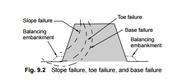
Provision of an inverted filter
The bearing capacity of the soil
is improved by the provision of a blanket of adequate thickness (inverted
filter, Fig. 9.3) between the ballast and the weak formation. The blanket
should be of a non-cohesive material with adequate bearing capacity to
withstand the load thereon. The blanketing material should conform to the
following specifications.
(a) The
liquid limit of the blanketing material should not be greater than 35 and the
plasticity index should not be greater than 15.
(b) The
blanketing material should have such a grain size that the fine soil from the
bottom does not mix up with the water. The material should, therefore, conform
to the specifications of an inverted filter.
(c) The
blanketing material should be well graded, starting from a fine size to a size
slightly smaller than stone ballast, the finer size lying at the bottom.
The inverted filter blanket is a
very effective method of improving the bearing capacity of the soil. It serves
as a barrier for the upward movement of the clay. It also provides a porous
medium to drain off the surface water. The blanket also works as a capillary
cut-off layer. The blanket can be inserted by imposing a traffic block of 4-5
hours or by temporarily operating only one line.
Improvement of surface drainage
Surface drainage can be improved
by diverting ground water, providing catch water drains, etc., as well as
draining the sub-surface structure.
Cement grouting
For cement grouting, a slurry or
grout of cement and sand is pumped into the embankment by pneumatic injections.
A 25-mm-diameter steel pipe is coupled with a rubber hose pipe of the same
diameter, and through this grout of cement and sand in the ratio of 1:2 to 1:6
is injected under a pressure of 60 psi with the help of a pneumatic hammer. The
injection points are kept close to both ends of the sleeper in a staggered
position at an interval of 1.5 m or so. Pumping is continued till the grout
appears through the ballast and reaches its top surface.
Cement grouting is considered to
be a very effective method of treating the subgrade. It fills the cracks,
preventing the water from flowing into the subgrade, and seals off the moisture
entering into it. The soil is stabilized and develops better properties and
strength.
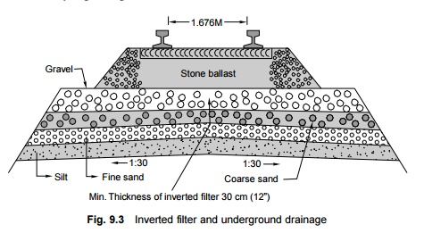
Sand piling
In sand piling (Fig. 9.4), a series of 30-cm-diameter holes
are drilled vertically inside and outside the rail to a depth of 2-3 m by means
of augers or other devices. The holes are then filled up with clean sand and
the track is resurfaced (Fig. 9.4). The sand piles are so arranged that the
cross-sectional area of the sand piles is about 20% of the formation area. Sand
piles compact the soil and provide mechanical support to the subgrade just like
wooden piles. The drainage of the subgrade also improves, as water rises to the
surface through the sand piles by capillary action and evaporates.
Deep screening of ballast and drainage of
water pockets
The problem of ballast pockets can
be tackled by assessing the depth of the penetration of the ballast in the
bank. For this purpose, about five vertical trial bores are drilled to get a
complete picture of the drainage condition of the sub-surface structure. Water
pockets can then be removed by any of the following methods, depending upon the
situation.
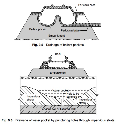
(a) If the
problem has just started, it can be remedied by deep screening and the
provision of a pervious layer of 30-60 cm on the cess. If necessary, the water
pockets can be drained using a perforated pipe drain inserted with the help of
a jack, as shown in Fig. 9.5.
(b) Cement
grouting can also be done to seal the water pockets in case the problem is in a
very small stretch. This method is, however, very expensive.
(c) If the
problem is extensive, a geological survey should be done to assess the type of
soil strata available. In case there is impervious soil under the water pocket,
it can be drained out using a perforated pipe (Fig. 9.5)-deep screening of the
ballast is done, the water pockets are drained out using a perforated pipe, and
then an inverted filter of about 30 cm thickness is provided.
(d) Counterfeit
drains are sometimes provided to drain the water pockets. Such drains are
generally 60 cm wide and spaced at intervals of 10 m or so, depending upon the
extent of the problem.
(e) Water may
also be held up in the ballast pockets by an impervious layer of soil over a
good pervious layer of soil of fissured strata. In this case the remedy lies in
drilling a tap hole in the thin impervious strata, allowing the water to go into the pervious subsoil, where
it gets drained automatically (Fig. 9.6).
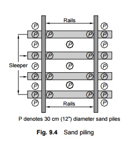
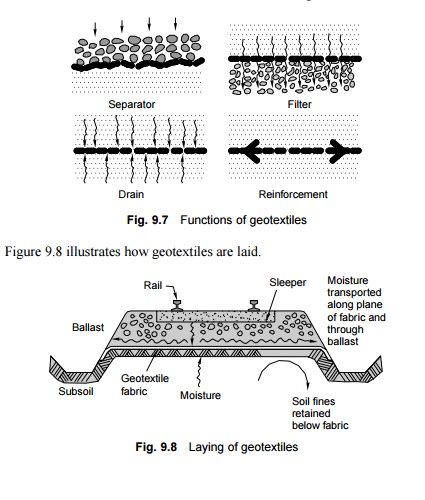
4 Soil Stabilization by Geotextiles
A new method of stabilization of
soil using geotextiles has recently been developed in many countries.
Geotextiles are made up of polymers and have the unique property of allowing
water, but not soil fines, to pass through. Geotextiles not only work as
separators and filters but also help drain the water and provide reinforcement
to the soil bed (Fig. 9.7).
A layer of geotextile is normally either laid directly below
the ballast or sandwiched between layers of sand. On Indian Railways, the
geotextile is proposed to be sandwiched between a 50-mm layer of sand on top
and a 25-mm layer of sand below so that the ballast does not rest directly on
the geotextile and incidences of tear and puncture are reduced.
Related Topics