Chapter: Optical Communication and Networking : Introduction
Electromagnetic mode theory for optical propagation
Electromagnetic mode theory for optical propagation
1. Electromagnetic waves
In order to obtain an improved model for the propagation of light in an optical fiber, elec-tromagnetic wave theory must be considered. The basis for the study of electromagnetic wave propagation is provided by Maxwell’s equations [Ref. 13]. For a medium with zero conductivity these vector relationships may be written in terms of the electric field E, magnetic field H, electric flux density D and magnetic flux density B as the curl equations:
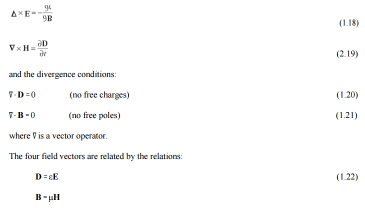
where ε is the dielectric permittivity and μ is the magnetic permeability of the medium. Substituting for D and B and taking the curl of Eqs (1.18) and 1.19) gives:
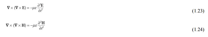
Then using the divergence conditions of Eqs (1.20) and (1.21) with the vector identity:
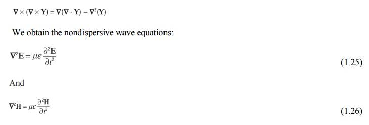
where∇2 is the Laplacian operator. For rectangular Cartesian and cylindrical polar coordinates the above wave equations hold for each component of the field vector, every component satisfying the scalar wave equation
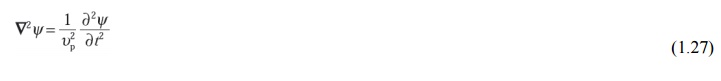
Where ψ may represent a component of the E or H field and up is the phase velocity (velocity of propagation of a point of constant phase in the wave) in the dielectric medium. It follows that:
Where μr and εr are the relative permeability and permittivity for the dielectric medium and μ0 and ε0 are the permeability and permittivity of free space. The velocity of light in free spacecis therefore:
If planar waveguides, described by rectangular Cartesian coordinates (x, y, z), or circular fibers, described by cylindrical polar coordinates (r, φ, z), are considered, then the Laplacian operator takes the form:
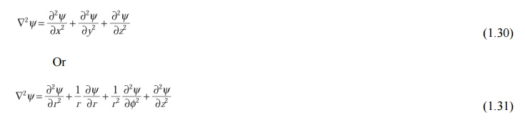
respectively.
It is necessary to consider both these forms for a complete treatment of optical propagation in the fiber, although many of the properties of interest may be dealt with using Cartesian coordinates.
The basic solution of the wave equation is a sinusoidal wave, the most important form of which is a uniform plane wave given by

where ω is the angular frequency of the field, t is the time, k is the propagation vector which gives the direction of propagation and the rate of change of phase with distance, while the components of r specify the coordinate point at which the field is observed. When λ is the optical wavelength in a vacuum, the magnitude of the propagation vector or the vacuum phase propagation constant k (where k = |k|) is given by:

It should be noted that in this case k is also referred to as the free space wave number.
2. Modes in a planar guide
The planar guide is the simplest form of optical waveguide. We may assume it consists of a slab of dielectric with refractive index n1 sandwiched between two regions of lower refractive index n2. In order to obtain an improved model for optical propagation it is useful to consider theinterference of plane wave components within this dielectric waveguide.
The conceptual transition from ray to wave theory may be aided by consideration of a plane monochromatic wave propagating in the direction of the ray path within the guide (see Figure 1.8(a)). As the refractive index within the guide is n1, the optical wavelength in this region is reduced to λ/n1, while the vacuum propagation constant is increased to n1k. When θ is the angle between the wave propagation vector or the equivalent ray and the guide axis, the plane wave can be resolved into two component plane waves propagating in the z and x directions, as shown in Figure 1.8(a).
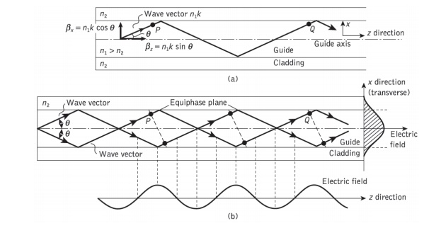
Figure 1.8 The formation of a mode in a planar dielectric guide: (a) a plane wavepropagating in the guide shown by its wave vector or equivalent ray – the wave vector is resolved into components in the z and x directions; (b) the interference of plane waves in the guide forming the lowest order mode (m = 0)
The component of the phase propagation in the Z direction is given by:

The component of the phase propagation constant in the x direction βx is:

The component of the plane wave in the x direction is reflected at the interface between the higher and lower refractive index media. When the total phase change* after two successive reflections at the upper and lower interfaces (between the points P and Q) is equal to 2mπ radians, where m is an integer, then constructive interference occurs and a standing wave is obtained in the x direction. This situation is illustrated in Figure 1.8(b), where the interference of two plane waves is shown. In this illustration it is assumed that the interference forms the lowest order (where m = 0) standing wave, where the electric field is a maximum at the center of the guide decaying towards zero at the boundary between the guide and cladding. However, it may be observed from Figure 1.8(b) that the electric field penetrates some distance into the cladding, a phenomenon which is discussed in Section 1.3.4.
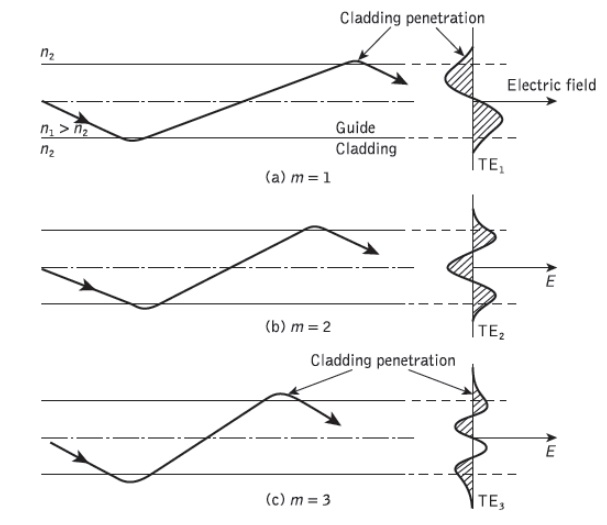
Figure 1.9 Physical model showing the ray propagation and the corresponding transverse electric (TE) field patterns of three lower order models (m =1, 2, 3) in the planar dielectric guide
Nevertheless, the optical wave is effectively confined within the guide and the electric field distribution in the x direction does not change as the wave propagates in the z direction. The sinusoidally varying electric field in the z direction is also shown in Figure 1.8(b). The stable field distribution in thex direction with only a periodic zdepen- dence is known as a mode. A specific mode is obtained only when the angle between the propagation vectors or the rays and the interface have a particular value, as indicated in Figure 1.8(b). In effect, Eqs (1.34) and (1.35) define a group or congruence of rays which in the case described represents the lowest order mode. Hence the light propagating within the guide is formed into discrete modes, each typified by a distinct value of θ.
To visualize the dominant modes propagating in the z direction we may consider plane waves corresponding to rays at different specific angles in the planar guide. These plane waves give constructive interference to form standing wave patterns across the guide following a sine or cosine formula. Figure 2.9 shows examples of such rays for m = 1, 2, 3, together with the electric field distributions in the x direction. It may be observed that mdenotes the number of zeros in this transverse field pattern. In this way m signifies the order of the mode and is known as the mode number.
When light is described as an electromagnetic wave it consists of a periodically varying electric field E and magnetic field H which are orientated at right angles to each other. The transverse modes shown in Figure 1.9 illustrate the case when the electric field is perpendicular to the direction of propagation and hence Ez = 0, but a corresponding component of the magnetic field H is in the direction of propagation. In this instance the modes are said to be transverse electric (TE). Alternatively, when a component of the E field is in the direction of propagation, but Hz =0, the modes formed are called transverse magnetic (TM). The mode numbers are incorporated into this nomenclature by referring to the Tem and TMm modes, as illustrated for the transverse electric modes shown in Figure 1.9. When the total field lies in the transverse plane, transverse electromagnetic (TEM) waves exist where both Ez and Hz are zero. However, although TEM waves occur in metallic conductors (e.g. coaxial cables) they are seldom found in optical waveguides.
3. Phase and group velocity
The envelope of the wave package or group of waves travels at a group velocity υg With in all electromagnetic waves, whether plane or otherwise, there are points of constant phase. For plane waves these constant phase points form a surface which is referred to as a wavefront. As a monochromatic lightwave propagates along a waveguide in the z direction these points of constant phase travel at a phase velocity υp given by

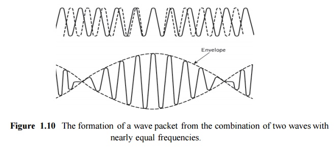
where ω is the angular frequency of the wave. However, it is impossible in practice to produce perfectly monochromatic lightwaves, and light energy is generally composed of a sum of plane wave components of different frequencies. Often the situation exists where a group of waves with closely similar frequencies propagate so that their resultant forms a packet of waves. The formation of such a wave packet resulting from the combination of two waves of slightly different frequency propagating together is illustrated in Figure 1.10. This wave packet does not travel at the phase velocity of the individual waves but is observed to move at a group velocity υg given by :
The group velocity is of greatest importance in the study of the transmission character- istics of optical fibers as it relates to the propagation characteristics of observable wave groups or packets of light. If propagation in an infinite medium of refractive index n1 is considered, then the propagation constant may be written as:

wherec is the velocity of light in free space. Equation (1.38) follows from Eqs (1.33) and (1.34) where we assume propagation in the z direction only and hence cos θ is equal to unity. Using Eq. (1.36) we obtain the following relationship for the phase velocity:
Similarly, employing Eq. (1.37), where in the limit δω/δβ becomes dω/dβ, the group velocity:
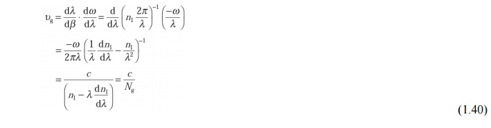
The parameter Ng is known as the group index of the guide.
Related Topics