Chapter: Mechanical : Design of Transmission Systems : Design of Transmission Systems for Flexible Elements
Design of Transmission Systems for Flexible Elements
DESIGN OF TRANSMISSION SYSTEMS FOR FLEXIBLE
ELEMENTS
V- BELT
Selection of V belts and pulleys
ü Determine your drive requirements.
How much power do you need to transmit and at what speed?
INTRODUCTION:
V- Belts
are one type of flexible connectors for transmitting power from one pulley to
another pulley. Whose center distance is approx. 3M.thier cross section is
trapezoidal. The belts are operated on groove pulleys.
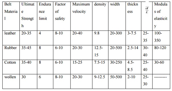
MATERIALS USED:
·
Cord
·
Fabric
·
Cotton
·
Rayon
POWER TRANSMISSION
Belts are
the cheapest utility for power transmission between shafts that may not be
axially aligned. Power transmission is achieved by specially designed belts and
pulleys. The demands on a belt drive transmission system are large and this has
led to many variations on the theme. They run smoothly and with little noise,
and cushion motor and bearings against load changes, albeit with less strength
than gears or chains. However, improvements in belt engineering allow use of
belts in systems that only formerly allowed chains or gears.
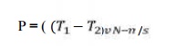
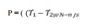
Power
transmitted between a belt and a pulley is expressed as the product of
difference of tension and belt velocity
P= (T1
-T2 ) v
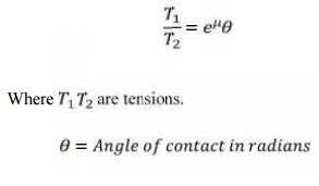
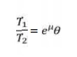
where, T1
and T2 are tensions in the tight side and slack side of the belt respectively.
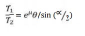
They are
related
as:
TYPES OF
V BELT
Generally
V belts are classified into various grades based on their power transmitting
capacity as A, B, C, D and E. the cross sectional areas are increased order
from A –E
SELECTION OF V BELTS AND PULLEYS
V belts
are designed based on
1. Fundamental
formula
2. Manufactures
catalogues
FUNDAMENTAL FORMULA:
2. Power Transmitted by belt
MANUFACTURES CATALOGUES
1. At first based on amount of power to be
transmitted , select the type of belt
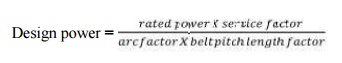
2. Calculate design power
Design power = 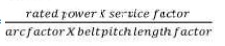
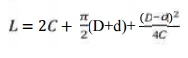
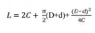
3. Pitch length
= 
4. Note inside length
5. Determine Belt rating
6. Design no of belts = 
7. Correct the center Length
8. Also determine parameters of V groove
pulleys using Manufactures data
Selection of Flat belts and pulleys
INTRTODUCTION
Flat Belts are one type of flexible connectors for
transmitting power from one pulley to another pulley. Whose center distance is
approx. 5-15m
CHARACTERISTICS OF BELT:
TYPES OF FLAT BELT DRIVES:
1. Open belt
drive
2. Cross
belt drive
3. Quarter
turn drive
4. Belt
drive with idler pulley
5. Belt
drive with many pulleys
DESIGN OF FLAT BELTS
1. Using
fundamental formula
2. Using
Manufactures catalogues
FUNDAMENTAL FORMULA:
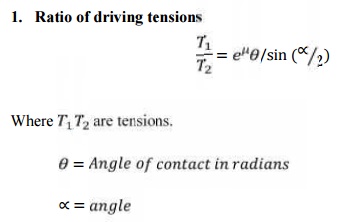
3. Ratio of driving tensions=
4. Power Transmitted by belt
MANUFACTURES CATALOGUES
1. How much
power to be transmitted
2. What may
be the power transmitting capacity
For
determining the design power and belt rating, we must consider certain factors
like service, arc of contactand so on.
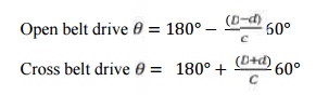
i. Arc of contact
ii. Load rating
The load
ratings have been developed for 180° of
arc of contact 10m/s belt speed per mm width.
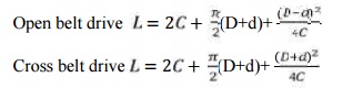
iii. Length
of belt
Open belt drive Cross belt drive
iv.
Belt
tensions
1. Belt of 3
plies – 1.5% of L
2. Belt of
4,5,6 plies – 1% of L
3. Belt of 8
plies – 0.5% of L
v.
Pulley
width
Generally
the pulleys should be slightly wider than belt width.
POWER TRANSMISSION
Belts are
the cheapest utility for power transmission between shafts that may not be
axially aligned. Power transmission is achieved by specially designed belts and
pulleys. The demands on a belt drive transmission system are large and this has
led to many variations on the theme. They run smoothly and with little noise,
and cushion motor and bearings against load changes, albeit with less strength
than gears or chains. However, improvements in belt engineering allow use of
belts in systems that only formerly allowed chains or gears. Power transmitted
between a belt and a pulley is expressed as the product of difference of
tension and belt velocity
P = (T1-
T2) v
where, T1
and T2 are tensions in the tight side and slack side of the belt
respectively. They are
related
as:
DESIGN PROCEDURE
1. From the
given conditions like power, type of working conditions, diameters of pulleys,
speed ratio etc, determine maximum power
Desin
power = rated power x service factor x arc of contact factor
Select
service factor based on nature of load
and applications from PSG data book
2. Decide
the type of belt
3. Then
calculate the belt rating
4. Find the
reqired width by design power by belt capacity and adopt the standard available
5. Determine
the length of belt based on type of drive and reduce certain amount length
6. Find out
the pulley dimension and draw the arrangement of belt drive.
Wire ropes and pulleys
SELECTION PROCEDURE
1. Based on
the given data like nature of application, duty etc, select the type of rope
2. Estimate
the design load by multiplying the dead weight by three times design factor.
3. 3. Determine the net cross sectional area of the
rope by choosing specific strength of wire.

4. Find out
the diameter of rope
5. Select
the next standard dia of rope and note down the max breaking strength
6. Compute
the load applied at normal working acceleration and starting etc. find out the actual
factor of safety by dividing the breaking strength by above loads
7. For safe
design the actual factor of safety should not be less than 5 at any
circumstances
8. Then
calculate the drum and pulley dimensions.
Selection of Transmission chains and Sprockets
SELECTION PROCEDURE
1. Depending upon the amount amount of
power to be transmitted and another working conditions such as available space,
chain speed, position of chain drive etc
2. Assuming the center distance between
the chaun sprockets interms of pitches
3. Calculate the developed load for
breaking the chain using expression as
4. For determining pitch, choose
suitable chain from PSG Data Book
5. Find out the actual factor of safety
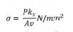
6. Determine the induced stress over the
projected area of the chain using the relation as
7. Find the length of chain and provide allowance for initial sagging.
=
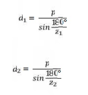
8. Evaluate the pitch diameter of pinion
sprocket (d1) and wheel sprocket (d2)
9. Draw a neat sketch of chain drive
with calculated specifications.
SOLVED PROBLEMS
1. Design a V – Belt drive to the following specifications Power
transmitted = 75kw
Speed of
driving wheel = 1440rpm
Speed of
driven wheel = 400rpm
Diameter
of driving wheel = 300mm
Center
distance = 2500mm
Service =
16hrs/day
Solution
For the
given power of 75 kw D type or E type belts are suited. Let us selected D type
belt.
Service
factor = 1.5 (for heavy duty and 16 hrs/ day with ac motor high torque)
Pitch
length
Now = 300
mm
The next
standard pitch length = 7648mm
Corresponding
inside length = 7569mm
Length
factor = 1.05
Arc of
contact
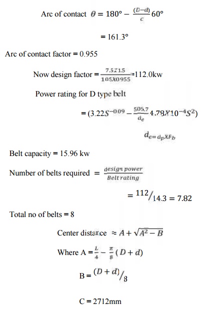
Initial
Tension = 0.75%L
Final
center distance = 2788 mm
Specification
Type of
belt = D7569 50 IS294
Number of
belts required = 8
Pitch
diameter of small pulley = 1080mm
Center
distance = 2788mm
2. Design
a Flat belt drive to transmit 25 kw at 720 rpm to an aluminium rolling machine
the speed reduction being 3.0. The distance between the shaft is 3m.Diameter of
rolling machine pulley is 1.2m.
Solution:
Given
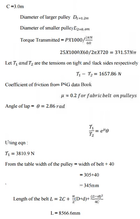
Specification
of the belt drive are
Dia of
motor pulley are = 400mm
Dia of
rolling machine pulley = 1200mm
Center
distance = 30000 mm
Width of
belt = 305mm
Width of
the belt = 345 mm
Width of
pulleys = 345mm
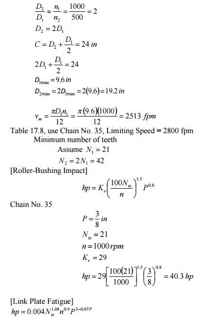
3.A
roller chain is to be used on a paving machine to transmit 30 hp from the 4-cylinder
Diesel engine to a counter-shaft; engine speed 1000 rpm, counter-shaft speed
500 rpm. The center distance is fixed at 24 in. The cain will be subjected to
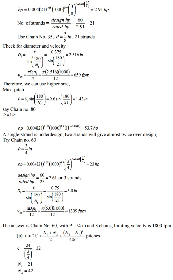
intermittent overloads of 100 %. (a) Determine the pitch and the number of
chains required to transmit this power. (b) What is the length of the chain
required? How much slack must be allowed in order to have a whole number of
pitches? A chain drive with significant slack and subjected to impulsive
loading should have an idler sprocket against the slack strand. If it were
possible to change the speed ratio slightly, it might be possible to have a
chain with no appreciable slack. (c) How much is the bearing pressure between
the roller and pin?
Solution:
(a) design hp = 2(30) = 60 hp intermittent

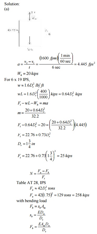
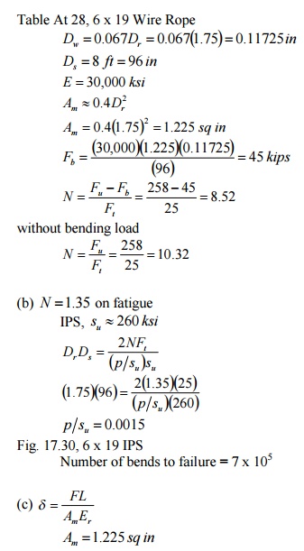
4.In a
coal-mine hoist, the weight of the cage and load is 20 kips; the shaft is 400
ft. deep. The cage is accelerated from rest to 1600 fpm in 6 sec. A single 6 x
19, IPS, 1 ¾ -in. rope is used, wound on an 8-ft. drum. (a) Include the inertia
force but take the static view and compute the factor of safety with and
without allowances for the bending load. (b) If
N =1.35 , based on fatigue, what
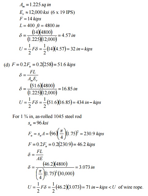
is the expected life? (c) Let the cage be at the bottom of the shaft and ignore the effect of the
rope’s weight. A load of 14 kips is gradually applied on the
6-kip
cage. How much is the deflection of the cable due to the load and the
additional energy absorbed? (d) For educational purposes and for a load of 0.2Fu , compute the energy that
this
400-ft
rope can absorb and compare it with that for a 400-ft., 1 ¾ -in.,
as-rolled-1045 steel rod. Omit the weights of the rope and rod. What is the
energy per pound of material in each case?
Related Topics