Chapter: Mechanical : Design of Transmission Systems : Design of Cam Clutches and Brakes
Design of Cam Clutches and Brakes
DESIGN OF CAM CLUTCHES AND BRAKES
Introduction
A clutch
is a machine member used to connect a driving shaft to a driven shaft so that
the driven shaft may be started or stopped at will, without stopping the
driving shaft. The use of a clutch is mostly found in automobiles. A little
consideration will show that in order to change gears or to stop the vehicle,
it is required that the driven shaft should stop, but the engine should
continue to run. It is, therefore, necessary that the driven shaft should be
disengaged from the driving shaft. The engagement and disengagement of the
shafts is obtained by means of a clutch which is operated by a lever.
Types of Clutches
Following
are the two main types of clutches commonly used in engineering practice :
1. Positive
clutches, and
2. Friction
clutches
Positive Clutches
The
positive clutches are used when a positive drive is required. The simplest type
of a positive clutch is a jaw or claw clutch. The jaw clutch permits one shaft
to drive another through a direct contact of interlocking jaws. It consists of
two halves, one of which is permanently fastened to the driving shaft by a sunk
key. The other half of the clutch is movable and it is free to slide axially on
the driven shaft, but it is prevented from turning relatively to its shaft by
means of feather key. A square jaw type is used where engagement and
disengagement in motion and under load is not necessary. This type of clutch
will transmit power in either direction of rotation. The spiral jaws may be
left-hand or right-hand, because power transmitted by them is in one direction
only. This type of clutch is occasionally used where the clutch must be engaged
and disengaged while in motion. The use of jaw clutches are frequently applied
to sprocket wheels, gears and pulleys. In such a case, the non-sliding part is
made integral with the hub.
Friction Clutches
A
friction clutch has its principal application in the transmission of power of
shafts and machines which must be started and stopped frequently. Its
application is also found in cases in which power is to be delivered to
machines partially or fully loaded. The force of friction is used to start the
driven shaft from rest and gradually brings it up to the proper speed without
excessive slipping of the friction surfaces. In automobiles, friction clutch is
used to connect the engine to the drive shaft. In operating such a clutch, care
should be taken so that the friction surfaces engage easily and gradually bring
the driven shaft up to proper speed. The proper alignment of the bearing must
be maintained and it should be located as close to the clutch as possible. It
may be noted that :
1. The
contact surfaces should develop a frictional force that may pick up and hold
the load with reasonably low pressure between the contact surfaces.
2. The heat
of friction should be rapidly
3. The
surfaces should be backed by a material stiff enough to ensure a reasonably
uniform distribution of pressure.
Material for Friction Surfaces
The
material used for lining of friction surfaces of a clutch should have the
following characteristics:
1. It should
have a high and uniform coefficient of friction.
2. It should
not be affected by moisture and oil.
3. It should
have the ability to withstand high temperatures caused by slippage.
4. It should
have high heat conductivity.
5. It should
have high resistance to wear and scoring.
DESIGN OF A DISC OR PLATE CLUTCH
Consider
two friction surfaces maintained in contact by an axial thrust (W) .Forces on a
disc clutch.
Let T =
Torque transmitted by the clutch,
p =
Intensity of axial pressure with which the contact surfaces are held
together,
r1 and r2
= External and internal radii of friction faces,
r = Mean
radius of the friction face, and
μ =
Coefficient of friction.
Consider
an elementary ring of radius r and thickness dr
We know
that area of the contact surface or friction surface = 2π r.dr
∴ Normal or axial force on the ring,
δW = Pressure × Area = p × 2 π r.dr
and the
frictional force on the ring acting tangentially at radius r,
∴ Frictional torque Fr = μ × δW = μ.p × 2 π r.dr
acting on the ring,
Tr = Fr × r = μ.p × 2 π r.dr × r = 2 π
μ p. r2.dr
We shall
now consider the following two cases :
1. When
there is a uniform pressure, and
2. When
there is a uniform axial wear.
1. Considering uniform pressure. When
the pressure is uniformly distributed over the entire
area of
the friction face then the intensity of pressure,
p = W / π
– [(r1)2 - (r2)2]
where W =
Axial thrust with which the friction surfaces are held together.
We have
discussed above that the frictional torque on the elementary ring of radius r
and thickness dr is
Tr = 2π
μ.p.r2.dr
∴Integrating this equation within the
limits from r2 to r1 for the total friction torque. Total frictional torque
acting on the friction surface or on the clutch,
2. Considering uniform axial wear. The
basic principle in designing machine parts that are subjected to wear due to
sliding friction is that the normal wear is proportional to the work of
friction. The work of friction is proportional to the product of normal
pressure ( p) and the sliding velocity (V). Therefore,∝ ∝
Normal wear Work
of friction p.V
or p.V =
K (a constant) or p = K/V ...(i)
It may be
noted that when the friction surface is new, there is a uniform pressure
distribution over the entire contact surface. This pressure will wear most
rapidly where the sliding velocity is maximum and this will reduce the pressure
between the friction surfaces.
This
wearing-in process continues until the product p.V is constant over the entire
surface. After this, the wear will be uniform.
Let p be
the normal intensity of pressure at a distance r from the axis of the clutch.
Since the intensity of pressure varies inversely with the distance, therefore
p.r = C
(a constant) or p = C/r ...(ii)
and the
normal force on the ring,
δW =
p.2πr.dr
= (C/r)
2π r dr
2πC.dr
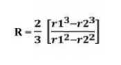
∴ Total force acing=on the friction surface,
R = (r1 + r2)/2
= Mean radius of the friction surface.
BRAKE
Introduction
A brake
is a device by means of which artificial frictional resistance is applied to a
moving machine member, in order to retard or stop the motion of a machine. In
the process of performing this function, the brake absorbs either kinetic
energy of the moving member or potential energy given up by objects being
lowered by hoists, elevators etc.
The
energy absorbed by brakes is dissipated in the form of heat. This heat is
dissipated in the surrounding air (or water which is circulated through the
passages in the brake drum) so that excessive heating of the brake lining does
not take place. The design or capacity of a brake depends upon the following
factors :
1. The unit
pressure between the braking surfaces,
2. The
coefficient of friction between the braking surfaces,
3. The
peripheral velocity of the brake drum
4. The
projected area of the friction surfaces, and
5. The ability
of the brake to dissipate heat equivalent to the energy being absorbed.
The major
functional difference between a clutch and a brake is that a clutch is used to
keep the driving and driven member moving together, whereas brakes are used to
stop a moving member or to control its speed.
Energy Absorbed by a Brake
The
energy absorbed by a brake depends upon the type of motion of the moving body.
The motion of a body may be either pure translation or pure rotation or a
combination of both translation and rotation. The energy corresponding to these
motions is kinetic energy. Let us consider these motions as follows :
1. When the
motion of the body is pure translation. Consider a body of mass (m) moving with
a velocity v1 m / s. Let its velocity is reduced to v2 m / s by applying the
brake. Therefore, the change in kinetic energy of the translating body or
kinetic energy of translation,
E1 =
(1/2) m [(v1)2 - (v2)2]
This
energy must be absorbed by the brake. If the moving body is stopped after
applying the brakes, then v2 = 0, and
E1 = (1/2)
m (v1)2
2. When
the motion of the body is pure rotation. Consider a body of mass moment of
inertia I (about a given axis) is rotating about that axis with an angular
velocity ω1 rad / s. Let its angular velocity is reduced to ω2 rad / s after
applying the brake. Therefore, the change in
kinetic
energy of the rotating body or kinetic energy of rotation,
E2 =
(1/2) I [(ω1)2 - (ω2)2]
This
energy must be absorbed by the brake. If the rotating body is stopped after
applying the brakes, then ω2 = 0, and
E1 = (1/2)
I (ω1)2
3. When
the motion of the body is a combination of translation and rotation. Consider a
body having both linear and angular motions, e.g. in the locomotive driving
wheels and wheels of a moving car. In such cases, the total kinetic energy of
the body is equal to the sum ∴of the kinetic energies of translation and
rotation.
Total
kinetic energy to be absorbed by the brake,
E = E1 +
E2
Sometimes,
the brake has to absorb the potential energy given up by objects being lowered
by hoists, elevators etc. Consider a body of mass m is being lowered from a
height h1 to h2 by applying the brake. Therefore the change in potential
energy,
E3 = m.g
(h1 – h2)
Heat to be Dissipated during Braking
The
energy absorbed by the brake and transformed into heat must be dissipated to
the surrounding air in order to avoid excessive temperature rise of the brake
lining. The upon the mass of the brake drum, the braking time and the heat
dissipation capacity of the brake. The highest permissible temperatures
recommended for different brake lining materials are given as follows :
1. For
leather, fibre and wood facing = 65 – 70°C
2. For
asbestos and metal surfaces that are slightly lubricated = 90 – 105°C
3. For
automobile brakes with asbestos block lining = 180 – 225°C
Since the
energy absorbed (or heat generated) and the rate of wear of the brake lining at
a particular speed are dependent on the normal pressure between the braking
surfaces, therefore it is an important factor in the design of brakes. The
permissible normal pressure between the braking surfaces depends upon the
material of the brake lining, the coefficient of friction and the maximum rate
at which the energy is to be absorbed. The energy absorbed or the heat
generated is given by
E = Hg =
μ.RN.v
= μ.p.A.v
(in J/s or watts) ...(i)
where μ = Coefficient of friction,
RN =
Normal force acting at the contact surfaces, in newtons,
p =
Normal pressure between the braking surfaces in N/m2,
A =
Projected area of the contact surfaces in m2, and
v =
Peripheral velocity of the brake drum in m/s.
The heat
generated may also be obtained by considering the amount of kinetic or
potential energies which is being absorbed. In other words,
Hg = EK +
EP
where EK = Total kinetic energy absorbed, and
EP =
Total potential energy absorbed.
The heat
dissipated (Hd) may be estimated by
Hd = C
(t1 – t2) Ar ...(ii)
where C =
Heat dissipation factor or coefficient of heat transfer in W /m2 / °C
t1 – t2 =
Temperature difference between the exposed radiating surface and the
surrounding air in °C, and
Ar = Area
of radiating surface in m2.
The value
of C may be of the order of 29.5 W / m2 /°C for a temperature difference of
40°C and increase up to 44 W/m2/°C for a temperature difference of 200°C.
The
expressions for the heat dissipated are quite approximate and should serve only
as an indication of the capacity of the brake to dissipate heat. The exact
performance of the brake should be determined by test.
It has
been found that 10 to 25 per cent of the heat generated is immediately
dissipated to the surrounding air while the remaining heat is absorbed by the
brake drum causing its temperature to rise. The rise in temperature of the
brake drum is given by
t = Hg /
(m.c) ...(iii)
where t = Temperature rise of the brake drum in °C
Hg = Heat
generated by the brake in joules,
m = Mass
of the brake drum in kg, and
c =
Specific heat for the material of the brake drum in J/kg °C.
In
brakes, it is very difficult to precisely calculate the temperature rise. In
preliminary design analysis, the product p.v is considered in place of
temperature rise. The experience has also shown that if the product p.v is
high, the rate of wear of brake lining will be high and the brake life will be
low. Thus the value of p.v should be lower than the upper limit value for the
brake lining to have reasonable wear life. The following table shows the
recommended values of p.v as suggested by various designers for different types
of service.
SOLVED PROBLEMs
1.
A single
plate clutch with both sides effective; is required to transmit 25 kw at 900
rpm. t hw outer diameter of the plate is 350 mm. the maximum intensity of
pressure over the friction surface is not to exceed 0.1 N/mm2 .
considering uniform wear criteria and assuming coefficient of friction as 0.25;
determine (i) the inner diameter of the plate (ii) axial force required to
engage the clutch.
Given;
P= 25 kw
; N =900 rpm ;2r =350 mm ; P max = 0.1 N/mm2 ; µ = 0.25
Sol:-
I.Inner diameter of the plate
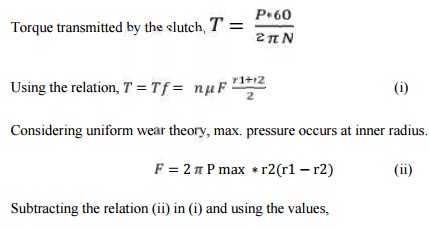
Subtracting
the relation (ii) in (i) and using the values,
r2
[(0.175)2 – r2] = 0.001689
0.031r2 - r2 3 = 0.001689 By trial and
error method,
r2 =
0.136m
II.Axial force required to engage the clutch (F)
= 2 π* 0.1
*106 * 0.136* (0.175 – 0.136 ) * 2
= 6665.2 N
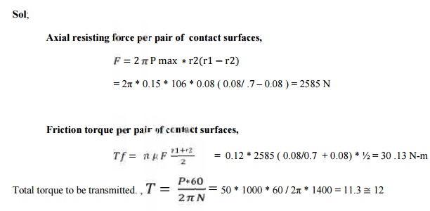
2. A multiple – disc clutch transmits 50
kw of power at 1400 rom. Axial intensity of pressure not to exceed 0.12 1 N/mm2, and the coefficient of friction
of the friction surfaces is 0.12. the inner radius of the discs is 80 mm, and
is .7 times the outer radius. Determine number of disc required to transmit the
given power. Assume uniform wear condition.
Given;
P = 60
kw; N = 1400rpm; P max = 0.15 N/mm2; µ = 0.12; r2 = 80mm;
r1 = r2/ 0.7
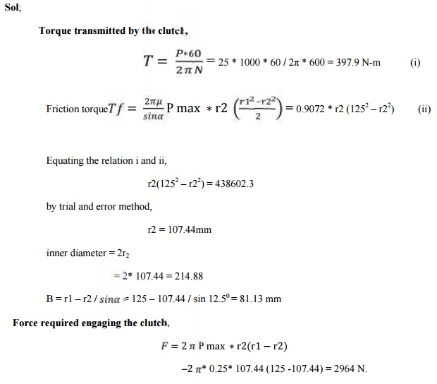
3. A cone clutch with asbestos friction lining,
transmits 25 kw at 600 rpm. The coefficient is 0.25 and the maximum intensity
of pressure is 0.25 N/ mm2. The semi cone angle is 12.50.
the outer diameter of friction lining is 250 mm . Considering uniform wear
theory. Determine
i. the inner diameter of the friction lining,
ii. the face width of friction lining and
iii.the force
required to engage to the clutch.
Given;
P = 25kw;
N = 600rpm; P max = 0.25 N/mm2; µ = 0.25; α = 12.50;
2r1 = 250mm
Sol;
4. A single block brake is shown in figure.
The diameter of the drum is 300 mm and the angle of contact is 900. If the operating force of 600N is
applied at the end of a lever and the coefficient of friction between the drum
and lining is 0.3 determine the torque that may be transmitted by the block
brake.
Page no.
27.16(machine desing)
Given;
L =
550mm; x= 250mm; a = 50mm; r = 2θ; 900 = π / 2 rad ; F = 600 N; µ =
0.3
Sol;
In the
present case the angle of contact is greater than 600. Hence, the
equivalent coefiicient of friction is given by,
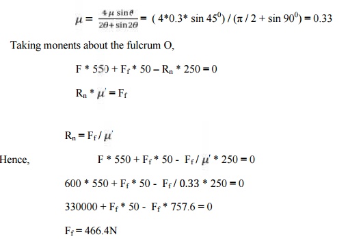
Torque
transmitted by the brake , Tf = Ff * r
= (466.4
* 150 ) / 1000 = 70N-m
Related Topics