Chapter: Embedded Systems Design : Software examples
Creating software state machines
Creating software state machines
With many real-time applications, a common approach taken with software
is first to determine how the system must respond to an external stimulus and
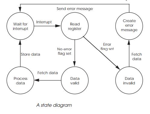
then to create a set of state diagrams which correspond with these definitions.
With a state diagram, a task or module can only exist in one of the states and
can only make a transition to another state provided a suitable event has
occurred. While these diagrams are easy to create, the software structure can
be difficult.
One way of creating the equivalent of software state dia-grams is to use
a modular approach and message passing. Each function or state within the
system — this can be part of or a whole state diagram — is assigned to a task.
The code for the task is extremely simple in that it will do nothing and will
wait for a message to arrive. Upon receipt of the message, it will decode it
and use the data to change state. Once this has been completed, the task will
go back to waiting for further input. The processing can involve other changes
of state as well. Referring back to the example, the incoming interrupt will
force the task to come out of its waiting state and read a particular register.
Depending on the contents of that register, one of two further states can be
taken and so on until the final action is to wait for another interrupt.
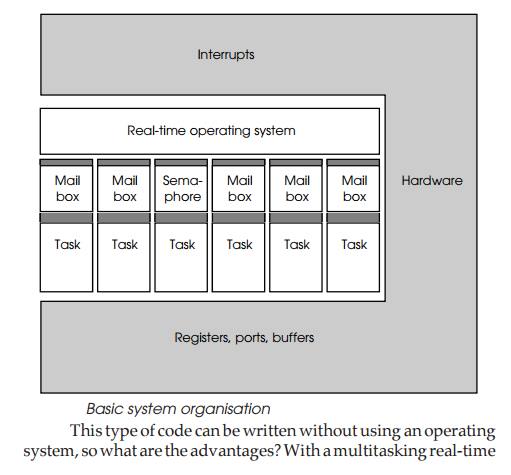
This type of code can be written without using an operating system, so
what are the advantages? With a multitasking real-time operating system, other
changes of state can happen in parallel. By allocating a task to each hardware
interrupt, multiple interrupts can easily be handled in parallel. The
programmer simply codes each task to handle the appropriate interrupt and the
operating system takes care of running the multiple tasks. In addition, the
operating system can easily resolve which interrupt or operation will get the
highest priority. With complex systems, the priorities may need to change
dynamically. This is an easy task for an operating system to handle and is
easier to write compared to the difficulty of writing straight line code and
coping with the differ-ent pathways through the software. The end result is
easier code development, construction and maintenance.
The only interface to the operating system is in providing the message
and scheduling system. Each task can use messages or semaphores to trigger its
operation and during its processing, generate messages and toggle semaphores
which will in turn trigger other tasks. The scheduling and time sharing of the
tasks are also handled by the operating system.
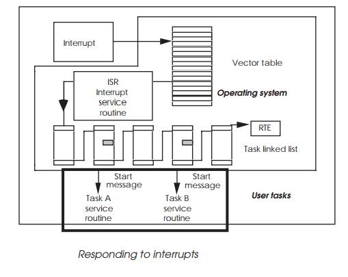
In the example shown overleaf, there are six tasks with their associated
mailboxes or semaphore. These interface to the real-time operating system which
handles message passing and sema-phore control. Interrupts are routed from the
hardware via the operating system, but the tasks can access registers, ports
and buffers directly.
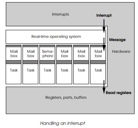
If the hardware generates an interrupt, the operating sys-tem will
service it and then send a message to the sixth task to perform some action. In
this case, it will read some registers. Once read, the task can now pass the
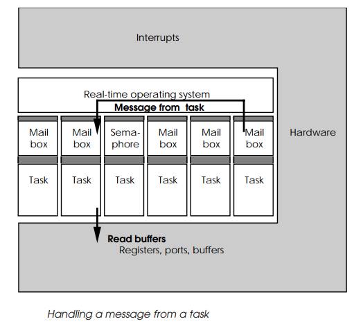
data on to another task for processing. This is done via the operating system.
The task sup plies the data either directly or by using a memory pointer to it
and the address of the receiving mail box. The operating system then places
this message into the mail box and the receiving task is woken up. In reality,
it is placed on the operating system scheduler ready list and allowed to
execute.
Once woken up, the receiving task can then accept the message and
process it. The message is usually designed to contain a code. This data may be
an indication of a particular function that the task is needed to perform. Using
this value, it can check to see if this function is valid given its current
state and, if so, execute it. If not, the task can return an error message back
via the operating system.
for_ever
{
Wait_for_ message(); Process message();
Discard_message();
}
Example task software loop
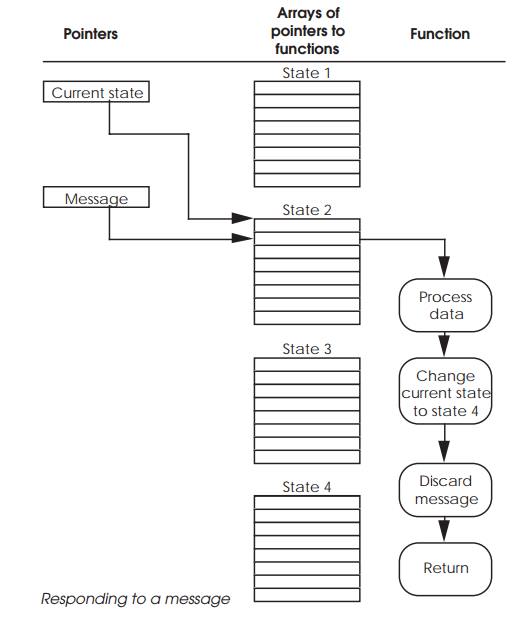
Coding this is relatively easy and can be done using a simple skeleton
program. The mechanism used to select the task’s response is via two pointers.
The first pointer reflects the current state of the task and points to an array
of functions. The second pointer is derived from the message and used to index
into the array of functions to execute the appropriate code. If the message is
irrelevant, then the selected function may do nothing. Alterna tively, it may
process information, send a message to other tasks or even change its own
current state pointer to select a different array of functions. This last
action is synonymous to changing state.
Priority levels
So far in this example, the tasks have been assumed to have equal
priority and that there is no single task that is particularly time critical
and must be completed before a particular window expires. In real applications,
this is rarely the case and certain routines or tasks are critical to meeting
the system requirements. There are two basic ways of ensuring this depending on
the facilities offered by the operating system. The first is to set the time
critical tasks and routines as the highest priority. This will nor-mally ensure
that they will complete in preference to others. However, unless the operating
system is pre-emptive and can halt the current task execution and swap it for
the time critical one, a lower priority task can still continue execution until
the end of its time slot. As a result, the time critical task may have to wait
up to a whole time slice period before it can start. In such worse cases, this
additional delay may be too long for the routine to complete in response to the
original demand or interrupt. If the triggers are asynchronous, i.e. can happen
at any time and are not particularly tied to any one event, then the lack of
pre-emption can cause a wide range of timings. Unfortunately for real-time
systems, it is the worst case that has to be assumed and used in the design.
An alternative approach offered by some operating sys-tems is the idea
of an explicit lock where the task itself issues directives to lock itself into
permanent execution. It will continue executing until it removes the lock. This
is ideal for very time critical routines where the process cannot be
interrupted by a physical interrupt or a higher priority task switch. The
disadvan-tage is that it can lead to longer responses by other tasks and in
some extreme cases system lock-ups when the task fails to remove the explicit
lock. This can be done either with the technique of special interrupt service
routines or through calls to the operating system to explicitly lock execution
and mask out any other inter-rupts. Real-time operating systems usually offer at
least one or other of these techniques.
Explicit locks
With this technique, the time critical software will make a system call
prior to execution which will tell the operating system to stop it from being
swapped out. This can also include masking out all maskable interrupts so that
only the task itself or a non-maskable interrupt can interrupt the proceedings.
The problem with this technique is that it greatly affects the performance of
other tasks within the system and if the lock is not removed can cause the task
to hog all of the processing time. In addition, it only works once the time
critical routine has been entered. If it has to wait until another task has
finished then the overall response time will be much lower.
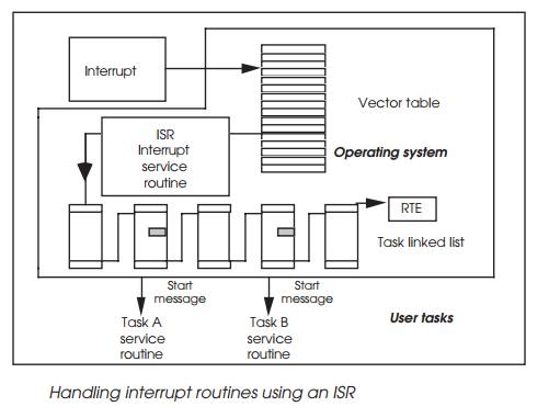
Interrupt service routines
Some operating systems, such as pSOS+, offer the facility of direct interrupt service routines or ISRs where
time critical code is executed directly. This allows critical software to
execute before other priority tasks would switch out the routines as part of a
context switch. It is effectively operating at a very low level and should not
be confused with tasks that will activate or respond to a message, semaphore or
event. In these cases, the operating system itself is working at the lower
level and effectively supplies its own ISR which in turn passes messages,
events and semaphores which activate other tasks.
The ISR can still call the operating system, but it will hold any task
switching and other activities until the ISR routine has completed. This allows
the ISR to complete without interruption.
It is possible for the ISR to send a message to its associated task to
start performing other less time critical functions associ-ated with the
interrupt. If the task was responsible for reading data from a port, the ISR
would read the data from the port and clear the interrupt and send a message to
its task to process the data further. After completing, the task would be
activated and effectively continue the processing started by the ISR. The only
difference is that the ISR is operating at the highest possible priority level
while the task can operate at whatever level the system demands.
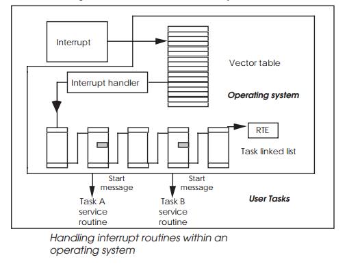
Handling interrupt routines within an operating system
Setting priorities
Given all these different ways of synchronising and control-ling tasks,
how do you decide which ones to use and how to set them up? There is no
definitive answer to this as there are many solutions to the same problem,
depending on the detailed charac-teristics that the system needs to exhibit.
The best way to illustrate this is to take an example system and examine how it
can be implemented.
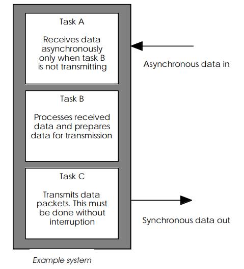
The system shown in the diagram below consists of three main tasks. Task
A receives incoming asynchronous data and passes this information onto task B
which processes it. After processing, task C takes the data and transmits it
synchronously as a packet. This operation by virtue of the processing and
syn-chronous nature cannot be interrupted. Any incoming data can fortunately be
ignored during this transmission.
Task A highest priority
In this implementation, task priorities are used with A having the
highest followed by C and finally B. The reasoning behind this is that although
task C is the most time critical, the other tasks do not need to execute while
it is running and therefore can simply wait until C has completed the
synchronous transmis-sion. When this has finished C can wake them up and make
itself dormant until it is next required. Task A with its higher priority is
then able to pre-empt B when an interrupt occurs, signalling the arrival of
some incoming data.
However, this arrangement does require some careful con-sideration. If
task A was woken up while C was transmitting data, task A would replace C by
virtue of its higher priority. This would cause problems with the synchronous
transmission. Task A could be woken up if it uses external interrupts to know
when to receive the asynchronous data. So the interrupt level used by task A
must be masked out or disabled prior to moving into a waiting mode and allowing
task C to transfer data. This also means that task A should not be allocated a
non-maskable interrupt.
Task C highest priority
An alternative organisation is to make task C the highest priority. In
this case, the higher priority level will prevent task A from gaining any
execution time and thus prevent any interrupt from interfering with the
synchronous operation. This will work fine providing that task C is forced to
be in a waiting mode until it is needed to transmit data. Once it has completed
the data transfer, it would remove itself from the ready list and wait, thus
allowing the other tasks execution time for their own work.
Using explicit locks
Task C would also be a candidate for using explicit locks to enable it
to override any priority scheme and take as much execution time as necessary to
complete the data transmission. The key to using explicit locks is to ensure
that the lock is set by all entry points and is released on all exit points. If
this is not done, the locks could be left on and thus lock out any other tasks
and cause the system to hang up or crash.
Round-robin
If a round-robin system was used, then the choice of execut-ing task
would be chosen by the tasks themselves and this would allow task C to have as
much time as it needed to transfer its data. The problem comes with deciding
how to allocate time between the other two tasks. It could be possible for task
A to receive blocks of data and then pass them onto task B for processing. This
gives a serial processing line where data arrives with task A, is proc-essed
with task B and transmitted by task C. If the nature of the data flow matches
this scenario and there is sufficient time be-tween the arrival of data packets
at task A to allow task B to process them, then there will be no problem.
However, if the arriving data is spread out, then task B’s execution may have
to be interleaved with task A and this may be difficult to schedule, and be
per-formed better by the operating system itself.
Using an ISR routine
In the scenarios considered so far, it has been assumed that task A does
not overlap with task C and they are effectively mutually exclusive. What
happens if this is not the case? It really depends on the data transfer rates
of both tasks. If they are slow, i.e. the need to send or receive a character
is slower than the context switching time, then the normal priority switching
can be used with one of the tasks allocated the highest priority. With its
synchronous communication, it is likely that it would be task C.
The mechanism would work as follows. Both tasks would be allocated their
own interrupt level with C allocated the higher priority to match that of its
higher task priority. This is important otherwise it may not get an opportunity
to respond to the interrupt routine itself. Its higher level hardware interrupt
may force the processor to respond faster but this good work could be negated
if the operating system does not allocate a time slice because an existing
higher priority task was already running.
If task A was servicing its own interrupt and a level C interrupt was
generated, task A would be pre-empted, task C would start executing and on
completion put itself back into waiting mode and thus allow task A to complete.
With a pre-emptive system, the worst case latency for task C would be the time
taken by the processor to recognise the external task C interrupt, the time
taken by the operating system to service it and finally the time taken to
perform a context switch. The worst case latency for task A is similar, but
with the addition of the worst case value for task C plus another context
switch time. The total value is the time taken by the processor to recognise
the external task A interrupt, the time taken by the operating system to
service it and, finally, the time taken to perform a context switch. The task C
latency and context switch time must be added because the task A sequence could
be interrupted and replaced at any time by task C. The extra context switch
time must be included for when task C completes and execution is switched back
to task A.
Provided these times and the time needed to execute the appropriate
response to the interrupt fit between the time critical windows, the system
will respond correctly. If not then time must be saved.
The diagram shows the mechanism that has been used so far which relies
on a message to be sent that will wake up a task. It shows that this operation
is at the end of a complex chain of events and that using an ISR, a lot of time
can be saved.
The interrupt routines of tasks A and C would be defined as ISRs. These
would not prevent context switches but will reduce the decision-making overhead
to an absolute minimum and is therefore more effective.
If the time windows still cannot be met, the only solution is to improve
the performance of the processor or use a second processor dedicated to one of
the I/O tasks.
Related Topics