Chapter: Embedded Systems Design : Real-time without a RTOS
Controlling from an external switch
Controlling from an external
switch
While the keyboard is fine for entering data and commands, it can be a
little tricky to use in a race car. For a start, the driver wears flame proof
gloves and this can make pressing a key a little difficult. Add to that the fact
that the PC must be securely mounted inside the car and not placed on the
passenger seat or driver’s lap and it makes this option a little difficult. One
solution would be to set the logging running and leave it like that and then
simply ignore or filter out the initial data so that it doesn’t appear. This is
a simple approach and indeed was used as a temporary measure but it is not
ideal. One of the problems is how to define and apply the filter. In practice,
all the interesting events occurred after the car left the start line. Looking
for wheel movement, followed by a traction control intervention signal could
identify the start line. By looking for these two signals, the start of the lap
or run could be identified and all data after this event kept. What is really
needed is to be able to have a simple switch to start and stop the data
logging.
With a desktop PC, this is not a problem as the joystick port can
provide this directly. IT uses four switches to indicate which way the stick is
moved and has additional switches for the firing triggers. Unfortunately,
laptops tend to be a little more conserva-tive in their design and usually do
not have a joystick port. They do however have a parallel port and this can be
used to read and write data to the outside world.
Normally the port is configured to drive a printer and sends bytes of
data to the device using eight pins. Other pins are used to implement a
handshake protocol to control the data flow and to provide additional status
information. As a result, these pins can provide both input and output
functions.
With the joystick port, the procedure is simple: connect the switch
between ground and the allocated pin and then read the respective bit to see
whether it is high or low (switch closed to ground). With the parallel port, it
is assumed that there is some hardware (typically in the printer) that will
provide the right signal levels. The usual method is to have a TTL level
voltage supply (5 volts) and apply this to the input pin to give a high or to ground
(0 volts) to indicate a low. Not difficult except that you need a separate
voltage supply.
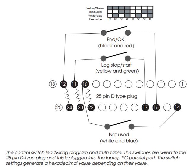
The trick used in this system was to allocate two pins to the input. One
pin is used as an output and is initialised by software to be set high. This
will provide a TTL high voltage on the output. This is then connected to the
input pin via a 10 kΩ resistor to limit the current
and protect the parallel port hardware. The switch is then connected to the
input pin and ground. When closed the pin is grounded and a logic 0 will be
read. When the switch is open, the pin is pulled high to the same voltage as
the output pin and a logic 1 will be read2. By reading the port and then looking at the value of the bit
associated with the input pin, the software can determine whether the switch is
open or closed. This can be used as a test condition within control loops to
define when the system should perform certain functions e.g. start and stop
logging and so on.
There is no reason why this cannot be repeated to provide several switch
inputs. The limit is really the number of output and input pins available. It
is important to prevent damage to the port hardware and that the current taken
from the output pin is minimised – hence the use of the resistor. This means
that it is best to allocate a separate output pin to provide the logical high
voltage per input pin. It is possible with some PCs to use this signal to work
on several input pins but is dependent on which of the parallel port silicon
chips have been used and whether they have been buffered. If high current ports
are assumed, then the system will be hardware dependent and may even damage PCs
with low current spec ports.
The implementation is not quite as simple due to some specific
modifications in the PC hardware design. While most pins are configured to be
active high i.e. when the associated bit in the port is set to a logic 1, the
pin voltage rises to a logic high, this is not the case for all. Some of the
pins are inverted to do the opposite for both the input and output. This means
that the values written to the ports to set the output pins high, are not
simply created by setting the bits high. Each bit needs to be checked to see if
it needs to be inverted or not. You can work this out but I took the easy way
out and used a freeware parallel port utility (http://www.lvr.com/ parport.htm
) that used a nice GUI to program the output pins and displayed their status on
screen. This gave the correct binary bit pattern which was then converted to
hexadecimal to derive the final value to program into the port.
Driving an external LED display
The parallel port output pins can drive a LED display to provide a
confirmation/status signal. While it is possible to con-nect a LED with a
current limiting resistor directly between the pin and ground signal, the power
limitations described in the previ-ous paragraph again come into play. It
should be assumed that the pin can only provide about 4 mA. This is enough to
light a LED but the luminance is not high and it can be difficult to see if the
LED is on or not. This can be solved by using a high intensity LED but their
power consumption is typically about 20 mA and exceeds the current safely
available from the parallel port.
The solution is to use a buffer pack that can supply higher current.
These are cheap and easy to use but do require an additional power supply to
drive the buffer.
With the ability to drive status LEDs, the software can perform other
functions such as indicating the amount of traction control intervention by
using this sample to drive a number of LEDs arranged in a bar graph. No
intervention and no LEDs are lit. Low level intervention and one LED is lit and
so on. This function is incorporated into the software but has not been
implemented in the final system.
Testing
Testing was done in two stages: in both stages, it would be necessary to
have the system connected to the data source to check that it was being logged
and stored correctly, both in workshop and real life conditions. For the first
stage, it is a little inconvenient to have a race car up and running generating
data to test the logging software. Instead, a simple data generator program was
written that behaved like the race car itself and generated dummy test patterns
which replicated the car’s behaviour. This meant that by using a second PC, the
data logging software could be plugged in and tested. Virtually all the
debugging was done this way.
This meant that the full functionality could be tested, in-cluding the
remote switches, without the car. This was fortuitous, as the car was not
always available due to it being worked on itself. This meant that the weekend
it took to develop the simulator software more than paid for itself by allowing
the development to continue independently of the car’s availability. This
approach parallels many used in other developments, including more com-plex
ones where instruction set simulators and similar tools are used to allow the
software development to continue in advance of true hardware availability.
With the PC-based testing completed, the system could be installed and
tested in the car itself. This was initially done in the garage while
stationary and then with a passenger using the system while the car was driven.
Once all this was completed, the system and car were taken to a race track and
the system used in anger during the day’s testing. This final testing revealed
several problems with the system.
Related Topics