Chapter: Civil : Prestressed Concrete Structures : composite construction
Concrete Structures: Serviceability Limit State
SERVICEABILITY LIMIT STATE
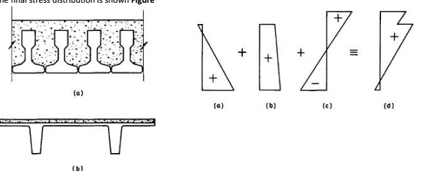
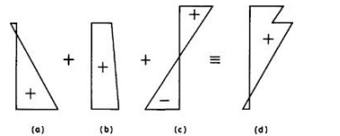
The stress distributions in the
various regions of the composite member are shown in Fig. 10.2(a)-(d). The
stress distribution in Fig. 10.2(a) is due to the self weight of the beam, with
the maximum compressive stress at the lower extreme fibre. Once the slab is in
place, the stress distribution in the beam is modified to that shown in Fig.
10.2(b), where the bending moment at the section, Md is that due to the
combined self weight of the beam and slab.
Once the concrete in the slab has
hardened and the imposed load acts on the composite section, the additional
stress distribution is shown in Fig. 10.2(c). This is determined by ordinary
bending theory, but using the composite section properties.
The final stress distribution is
shown Figure
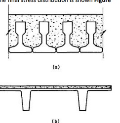
Stress distribution within a
composite section. The floor slab shown in Fig. 10.3 comprises precast
pretensioned beams and an in situ concrete slab. If the span of the beams is 5
m and the imposed load is 5 kN/m2 (including finishes), determine the stress
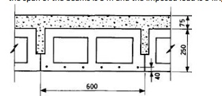
distributions at the various load
stages. Assume all long-term losses have occurred before the beams are erected
and that the net force in each wire is 19.4 kN. Section properties of the
beams:
Ac=1.13�105 mm2
Ic=7.5�108 mm4
Zt=Zb=6�106 mm3.
Eccentricity of the wires=125?40=85 mm.
(i)
Self
weight of the beams=0.113�24
=2.7 kN/m.
Mo=(2.7�52)/8
=8.4 kNm.
Total prestress force after all
losses have occurred is given by
�Po=6�19.4
=116.4 kN.
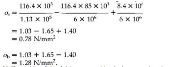
The stress distribution in the beams
is thus given by
(ii)
The
weight of the slab is supported by the beams acting alone, so that
d=8.4+0.075�0.6�24�52/8 =11.8 kNm. The stress distribution within the beams is
now given
(iii)
(iii)
The imposed load of 5 kN/m2 is supported by the composite section and the
section properties of this are now required. To find the neutral axis of the
composite section, taking moments about the soffit of the beams gives
(1.13�105+75�600)y=(1.13�105�125+75�600�288)
?y=171 mm.
Icomp=7.5�108+1.13�105 (171-125)2+(753�600)/12+(75�600)/(288-171)2
=1.63�109 mm4.
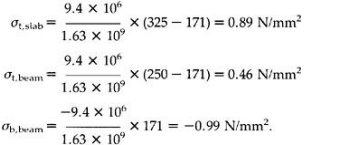
The imposed load bending moment, (Mdes?Md)=0.6�5�52/8
=9.4 kNm. The stress distribution within the composite
section under this extra bending moment
is given by
The maximum compressive stress occurs at the upper
fibres of the beams, but is significantly lower than the level of stress had
the beam carried the total imposed load alone. This explains the advantage of
inverted T-sections in composite construction, where only a small compression
flange is required for bending moments Mo and Md, the
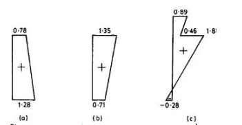
Stress distribution for composite section in Example
10.1 (N/mm2): (a) beam; (b)beam and slab; (c) beam and slab and imposed load.
compression flange for bending moment Mdes being
provided by the slab. The maximum compressive stress in the slab is much lower
than in the beam and, for this reason, in many composite structures a lower
grade of concrete is used for the in situ portion. The modulus of elasticity
for this concrete is lower than that for the beam and this effect can be taken
into account in finding the composite section properties by using an
approximate modular ratio of 0.8.
The in situ slab in Example 10.1 lies above the
composite section neutral axis and, therefore, the slab is in compression over
its full depth under the total design load. However, for composite sections as
shown in Fig. 10.1(a) the in situ portion of the section extends well below the
neutral axis, so that the lower region is in tension. If the tensile strength
of this concrete is exceeded then the composite section properties must be
determined on the basis of the in situ section having cracked below the neutral
axis.
Related Topics