Chapter: Automation, Production Systems, and Computer Integrated Manufacturing : Group Technology and Cellular Manufacturing
Cellular Manufacturing
CELLULAR
MANUFACTURING
Whether
part families have been determined by visual inspection. parts classification
and coding, or production flow analysis, there is advantage in producing those
parts using group technology machine cells rather than a traditional process type
machine layout. When the machines are grouped. the term cellular manufacturing
is used to describe this work organization. Cellular
manufacturing is an application of group technology in which dissimilar
machines or processes have been aggregated into cells, each of which is
dedicated to the production of a part or product family or a limited group of
families. The typical objectives in cellular manufacturing are similar to those
of group technology:
To
shorten manufacturing lead times, by reducing setup, workpart
handling, waiting times, and batch
sizes
To reduce
work-in-process inventory. Smaller batch sizes and shorter lead times reduce
work-in-process.
To improve
quality. This is
accomplished by allowing each cell to specialize in producing a smaller number
of different parts. This reduces process variations.
To
simplify production scheduling. The similarity among parts in the
family reduces the complexity of
production scheduling. Instead of scheduling parts through a sequence of machines
in a process-type shop layout, the parts are simply scheduled though the cell.
To reduce
setup times. This is accomplished by using group tooling (cutting tools,
jigs, and fixtures) that have been designed to process the part family,
rather than part tooling, which is designed for an individual part. This
reduces the number of individual tools required as well as the time to change
tooling between parts.
Additional
reasons for implementing cellular manufacturing are given in Table 15.7. In
this section, we consider several aspects of cellular manufacturing and the
design of machine ceils.
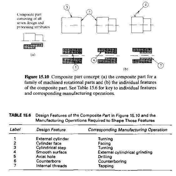
Composite Part
Concept
Part
families are defined by the fact that their members have similar design and/or
manufacturing features. The composite part concept takes this part family
definition to its logical conclusion. It conceives of a hypothetical part, a composite part for a given family, which
includes all of the design and manufacturing attributes of the family. In
general. an individual part in the family will have some of the features that
characterize the family but not all of them. The composite part possesses all
of the features.
There is
always a correlation between part design features and the production operations
required 10 generate those features. Round holes are made by drilling,
cylindrical shapes are made by turning, flat surfaces by milling, and so on. A
production cell designed for the part family would include those machines
required to make the composite part. Such a cell would be capable of producing
any member of the family, simply by omitting those operations corresponding to
features not possessed by the particular part. The cell would also be designed
to allow for size variations within the family as well as feature variations.
To
illustrate, consider the composite part in Figure 15.1O(a).1l represents a
family of rotational parts with features defined in Figure 15.1O(b). Associated
with each feature is a certain machining operation as summarized in Table 15.6.
A machine cell to produce this

part
family would be designed with the capability to accomplish all seven operations
required to produce the composite pan (the last column in the table). To
produce a specific member of the family, operations would be included to
fabricate the required features of the part. For parts without all seven
features, unnecessary operations would simply be omitted. Machines, fixtures,
and tools would be organized for efficient flow of work-parts through the cell,
In
practice, the number of design and manufacturing attributes is greater than seven,
and allowances must be made for variations in overall size and shape of the
parts in the family. Nevertheless, the composite part concept is useful for
visualizing the machine cell design problem.
Machine Cell Design
Design of
the machine cell is critical in cellular manufacturing. The cell design determines
to a great degree the performance of the cell. In this subsection, we discuss
types of machine cells, cell layouts, and the key machine concept.
Types
of Machine Cells and Layouts. GT manufacturing cells can be
classified according to the number of machines and the degree to which the material
flow is mechanized between machines. In our classification scheme for
manufacturing systems (Section 13.2), all GT cells are classified as type X in
terms of part or product variety (Section 13.2.4, Table 13.3). Here we identify
four common GT cell configurations (with system type identified in parenthesis
from Section 13.2):
single
machine cell (type I M)
group machine cell with manual handling
(type n M generally, type III M less common)
group machine
cell with semi-integrated handling (type II M generally, type III M less
common)
flexible
manufacturing cell or flexible manufacturing system (type IT A generally, type
III A less common)
As its
name indicates, the single machine cell
consists of one machine plus supporting fixtures and tooling. This type of cell
can be applied to work-parts whose attributes allow them to be made on one
basic type of process, such as turning or milling. For example, the composite part of Figure 15.10 could be produced
on a conventional turret lathe, with the possible exception of the cylindrical
grinding operation (step 4)
The group machine cell with manual handling
is an arrangement of more than one machine used collectively to produce one or
more part families. There is no provision for mechanized parts movement between
the machines in the cell. Instead, the human operators who run the cell perform
the material handling function. The cell is often organized into a U shaped
layout, as shown in Figure 15.11. This layout is considered appropriate when
there is variation in the work flow among the parts made in the cell. It also
allows the multifunctional workers in the cell to move easily between machines
[29].
The group
machine cell with manual handling is sometimes achieved in a conventional
process type layout without rearranging the equipment. This is done simply by
assigning certain machines to be included in the machine group and restricting
their work to specified part families. This allows many of the benefits of
cellular manufacturing to be achieved without the expense of rearranging
equipment in the shop. Obviously, the material handling benefits of OT are
minimized with this organization.
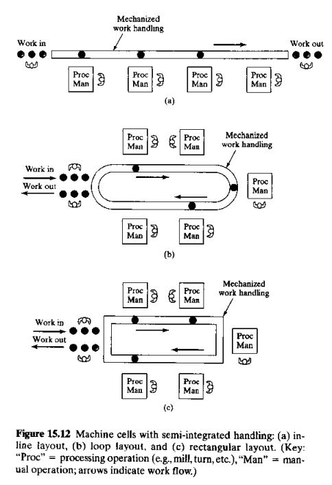
The group machine cell with semi integrated
handling uses a mechanized handling system, such as a conveyor, to move
parts between machines in the cell. The flexible
manufacturing system (FMS) combines a fully integrated material handling
system with automated processing stations. The FMS is the most highly automated
of the group technology machine cells. The following chapter is devoted to this
form of automation, and we defer discussion till then.
A variety
of layouts are used in GT cells, The U-shape, as in Figure 15.11, is a popular configuration
in cellular manufacturing. Other GT layouts include inline, loop, and
rectangular, shown in Figure 15.12 for the case of semi integrated handling.
Determining
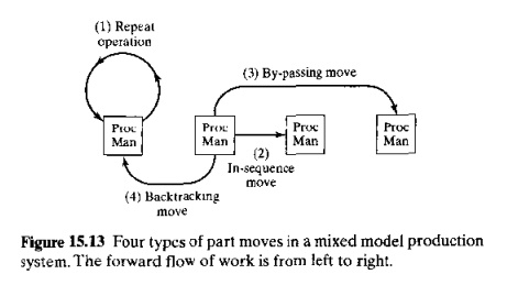
the most appropriate cell layout depends on the routings of parts produced in
the cell. Four types of part movement can be distinguished in a mixed model
part production system. They are illustrated in Figure 15.13 and are defined as
follows, where the forward direction of work flow is defined as being from left
to right in the figure:(l) repeat
operation, in which a consecutive operation is carried out on the same
machine, so that the part does not
actually move; (2) in-sequence move,
in which the part moves from the current machine to an immediate neighbor in
the forward direction; (3) bypassing
move, in which the part moves forward from the current machine to another
machine that is two or more machines ahead; and (4) backtracking move, in which the part moves from the current machine
in the backward direction to another machine.
When the
application consists exclusively of in sequence moves, then an inline layout is
appropriate. A V-shaped layout also works well here and has the advantage of
closer interaction among the workers in the cell. When the application includes
repeated operations, then multiple stations (machines) are often required. For
cells requiring bypassing moves, the U-shape layout is appropriate. When
backtracking moves are needed, a loop or rectangular layout is appropriate to
accommodate recirculation of parts within the cell. Additional factors that
must be accounted for in the cell design include:
Quantity
of work to be done by the cell. This includes the number of parts
per year and the processing (or
assembly) time per part at each station. These factors determine the workload
that must be accomplished by the cell and therefore the number of machines that
must be included, as well as total operating cost of the cell and the
investment that can be justified .
Part
size, shape, weight, and other physical attributes. These
factors determine the size and type
of material handling and processing equipment that must be used.
Key
Machine Concept. In some respects, a GT machine cell operates like a
man.
ual
assembly line (Chapter 17), and it is desirable to spread the workload evenly
among the machines in the cell as much as possible. On the other hand, there is
typically a certain rnachine in a cell (or perhaps more than one machine in a
large cell) that is more expensive to operate than the other machines or that
performs certain critical operations in the plant This machine is referred to
as the key machine. It is important
that the utilization of this key machine be high. even if it means that the
other machines in the cell have relatively low utilization. The other machines
are referred to as supporting machines,
and they should be organized in the cell to keep the key machine busy. In a
sense, the cell is designed so that the key machine becomes the bottleneck in the
system.
The key
machine concept is sometimes used to plan the GT machine cell. The approach is
to decide what parts should be processed through the key machine and then
determine what supporting machines are required to complete the processing of
those parts.
There are
generally two measures of utilization that are of interest in a GT cell: the
utilization of the key machine and the utilization of the overall cell. The
utilization of the key machine can be measured using the usual definition
(Section 2.4.3). The utilization of each of the other machines can also be
evaluated similarly. The cell utilization is obtained by taking a simple
arithmetic average of all the machines in the cell. One of the exercise
problems at the end of the chapter serves to illustrate the key machine concept
and the determination of utilization
Related Topics