Chapter: Automation, Production Systems, and Computer Integrated Manufacturing : Automotion and Control Technologies
Advanced Automation Functions
ADVANCED AUTOMATION
FUNCTIONS
In
addition to executing work cycle programs, an automated system may be capable
of executing advanced functions that are nOI specific to a particular work
unit. In general, the functions are concerned with enhancing the performance
and safety of the equipment. Advanced automation functions include the
following: (1) safety monitoring, (2) maintenance and repair diagnostics, and
(3) error detection and recovery.
Advanced
automation function> are made possible by special subroutines included in
the program of tnsttuctluns. In some cases, the runcnons provide information
only and
do not
involve any physical actions by the control system, An example of this case
includes reporting a list of preventive maintenance tasks that should be
accomplished. Any actions taken on the basis of this report are decided by the
human operators and managers of the system and not by the system itself 11\ other cases, the program of
instructions must be physically executed by means of the control system using
available actuators. A simple example of this case is a safety monitoring
system that sounds an alarm when a human worker gets dangerously close to the
automated system.
Safety Monitoring
One ot
the significant reasons for automating a manufacturing operation is to remove
workcr{s) from a hazardous working environment. An automated system is often
installed to perform a potentially dangerous operation that would otherwise be
accomplished manually by human workers '.However, even in automated systems.
wo~kers arestill needed to service
the system. at periodic time intervals If not fulltime. Accordingly. it is
important that the automated system
be designed to operate safely when workers arc in attendance. In addition.rt is
essential that the automated system carry QUills proCI;:SS in a way that is not
selfdestructive. Thus. there are two reasons for providing an automated system
with a safety monitoring capability: (1) to protect human workers in the
vicinity of the system ami (2) to protect the equipment associated with the
system.
Safety
monitoring means more than the conve.ntionalsafety measures til ken in a ill: al· ufacturing operation, such as protective shields around the operation
or the kinds of manual devices that might be utilized by human workers. such as emergency
stop buttons. Safety moniroringin an automated system
involves the use or sensors to track the system's operation and identify
conditions and events that are unsafe or potentially unsafe. The safety
monitoring system is programmed to respond to unsafe conditions in some
appropriate way. Possible responses to various hazards might include one or
more of the following:
complete stoppage
of the automated system
sounding an alarm
reducing the operating
speed of the process
taking
corrective actions to recover
from the safety violation
This last
response is the most sophisticated and is suggestive of an intelligent machine
performing some advanced strategy, This kind of response is applicable to a
variety of possible mishaps, not necessarily confined to safety issues, and is
called error detection and recovery (Section 3.2.3).
Sensors
for safety monitoring range from very simple devices to highly sophisticated
systems. The topic of sensor technology is discussed in Chapter 5 (Section
5.1). The following list suggests some of the possible sensors and their
applications for safety monitoring:
Limit
switches to detect proper positioning of a part in a workholding device so that
the processing cycle can begin.
Photoelectric
sensors triggered by the interruption of a light beam; this could be used to
indicate that a part is in the proper position or to detect the presence of a
human intruder into the work cell.
Temperature
sensors to indicate that a metal workpart is hot enough to proceed with a hot
forging operation. If the workpart is not sufficiently heated, then the metal's
duetutty may be too low, and the forging dies might be damaged during the
operation.
Heat or smoke
detectors to sense fire hazards.
Pressuresensitive floor pads to detect human
intruders into the work celL
Machine vision systems to supervise
the automated system and its surroundings.
It should
be mentioned that a given safety monitoring system is limited in its ability to
respond to hazardous conditions by the possible irregularities that have been
foreseen by the system designer. If the designer h as not anticipated a
particular hazard, and consequently has not provided the system with the
sensing capability to detect that hazard, then the safety monitoring system
cannot recognize the event if and when it occurs.
Maintenance and Repair Diagnostics
Modem
automated production systems are becoming increasingly complex and
sophisticated, thus complicating the problem of maintaining and repairing them.
Maintenance and repair diagnostics refers to the capabilities of an automated
system to assist in the identi fication of the source of potential or actual
malfunctions and failures of the system. Three. modes of operation are typical
of a modern maintenance and repair diagnostics subsystem
SWills monitoring, In the statu, monitoring mode, the
diagnostic subsystem moniton and records the status of key sensors and
parameters of the system during norma. operation. On request, the diagnostics
subsystem can display any of these values and provide an interpretation of
current system status, perhaps warning of an imminert failure
Failure diagnostics. The
failure diagnostics mode is invoked when a malfunction or failure oCCUTS. Its purpose is to interpret the current values of
the monitored van. ables and to analyze the recorded values preceding the
failure so that the cause of the failure can be identified
3 Recommendation of repair
proceaure.uv the third mode of operation. the subsystem provides a recommended procedure to the
repair crew as to the steps that should be taken to effect repairs. Methods for
developing the recommendations are sometimes based on the use of expert systems
in which the collective judgments of many repair experts arc pooled and
incorporated into a computer program that uses artificial intelligence
techniques.
Status
monitoring serves two important functions if"!machine diagnostics: (I)
providing information for diagnosing a current failure and (2) providing data
to predict a future malfunction or failure. first, when a failure of the
equipment has occurred, it is usually difficult for the repair crew to
determine the reason for the failure and what steps should be taken 10 make
repairs. It is often helpful to reconstruct the events leading up to the
failure. The computer is programmed to monitor and record the variables and to draw logical inferences from their
values about the reason for the malfunction, This diagnosis helps the repair
personnel make the necessary repairs and replace the appropriate components.
This is
especially helpful in electronic repairs where it is often difficult to
determine on the basis of visual inspection which components have failed
The
second function of status monitoring is to identify signs of an impending
failure, so that the affected components can be replaced before failure
actually causes the system to go down. These part replacements can be made
during the night shift or other time when the process is not operating. with
the result that the system experiences [10loss of regularoperation
Error Detection
and Reovery
In the
operation of any automated system, there are hardware malfunctions and
unexpected events that occur during operation. These events can result in
costly delays and loss of production until the problem has been corrected and
regular operation is restored. Traditionally. equipment malfunctions are
corrected by human workers, perhaps with the aid of a maintenance and repair
diagnostics suhroutine. With the increased use of computer control for
manufacturing processes, there is a trend toward using the control computer not
only to diagnose the malfunctions but also to automatically take the necessary
corrective action to restore the system to normal operation. The term error detection and recovery is used
when the computer performs these functions,
Error Detection. A,
indicated by the term. error detection lind recovery consists of two steps: (1) error detection and (2)
error recovery. The error defection step
uses the automated svstem's available sensor systems to determine when a
deviation or malfunction has occurred, correctly interpret the sensor
signal(s), and classifythe error. Design of the error detection subsystem must
begin with 11 classification of the possible errors that can occur during
system operation. The errors in a manufacturing process tend to be vcry
application specific. They must be anticipated in advance in order to select
sensors that will enable their detection
In
analyzing a given production operation, the possible errors can be classified
into one of three general categories: (1) random errors, 1'2)systematic errors.
and (3) aberrations, Random errors occur
as a result of the normal stochastic nature of the process. These errors occur
when the process is in statistical control (Section 21.1). Large variations in
part dimensions, even when the production process is in statistical control,
can cause problems in downstream operations. By detecting these deviations on a
partbypart basis, corrective action can be taken in subsequent operations, Systematic errors are those that result
from some assignable cause such as a change in raw material properties or a
drift in an equipment setting. These errors usually cause the product to
deviate from specifications so as to be unacceptable in quality terms. Finally.
the third type of error. aberrations,
results from either an equipment failure or a human mistake. Examples of
equipment failures include fracture of a mechanical shear pin, bursts in a
hydraulic line, rupture of a pressure vessel, and sudden failure of a cutting
tool. Examples of human mistakes include errors in the control program,
improper fixture setups, and substitution of the wrong raw materials,
The two
main design problems in error detection are: (1) to anticipate all of the
possible errors that can occur in a given process and (2) to specify the appropriate sensor systems and
associated interpretive software so that the system is capable of recognizing
each error. Solving the first problem requires a systematic evaluation of the
possibilities under each of the three error classifications. If the error has
not been anticipated, then the error detection subsystem cannot correctly
detect and identify it.
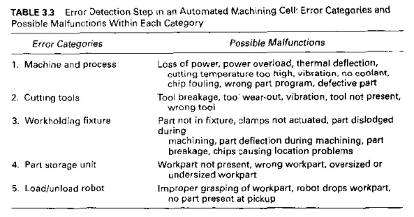
EXAMPLE 3.2 Error
Detection in an Automated Machining
Cell
Consider
an automated cell consisting of a CNC machine tool, a parts storage unit, and a
robot for loading and unloading the parts between the machine and the storage
unit. Possible errors that might affect this system can be divided into the
following categories: (1) machine and process, (2) cutting tools, (3)
workholding fixture, (4) parI storage unit, and (5) load/unload robot. Develop
a list of possible errors (deviations and malfunctions) that might be included
in each ofthcse five categories.
Solution: A list of possible errors in
the machining cell is presented in Table 3.3.
Error Recovery. Error
reCIJVPfY is
concerned with applying the necessary corrective
action to overcome the error and bring the system back to normal operation.
The problem of designing an error
recovery system focuses on devising appropriate strategies and procedures that
will either correct or compensate for the variety of errors that can occur in
the process. Generally, a specific recovery strategy and procedure must be
designed for each different error, The types of strategies can he classified as
follows:
l , Make adjustments at the end of the current
work cycle. When the current work cycle is completed. the part program
branches to a corrective action subroutine specifically
designed
for the error detected, executes the subroutine, and then returns to the work
cycle program. this action reflects a low level of urgency and is most commonly
associated with random errors in the process.
Make udjusnnents during IIII' curreW cycle. I his
general1y indicates a higher level of urgency than the preceding lype.
In this case, the action to correct or compensate for the detected error is
initiated a~ soon as the error is detected. However, it must be possible to
accomplish the designated corrective action while the work cycle is still being
executed
• Stop the prnc<'ss {O invoke corrective action. In this
case, the deviation or malfunction requires
that the execution of the work cycle be suspended during corrective action. It i~assumed that the system is
capable of automatically recovering from the error without human assistance.
Atthe end of the corrective action, the regular work cycle Is continued.
• Stop (III:process and call for help. In this
case, the error requiring stoppage of the process cannot he resolved through automated recovery procedures. This
situation arises because: (I) the automated cell is not enabled to correct the
problem or (2) the error cannot be classified into the predefined list of errors.
In either case, human assistance is required to correct the problem and restore
the system to fully automated operation.
Error
detection and recovery requires an interrupt system (Section 4.3.2). When an
error in the process is sensed and identified, an interrupt in the current
program execution is invoked to branch to the appropriate recovery subroutine,
This is done either at the end of the current cycle (type 1 above) or
immediately (types 2, 3,and 4).At the completion of the recovery procedure,
program execution reverts back to normal operation.
EXAMPLE 3.3 Error Recovery in
811Autom8ted Machining CeU
lor the automated cell uf Example 3.2. develop a
list of possible corrective actions that might be taken by the system to
address certain of the errors.
Related Topics