Chapter: Mechanical : Mechatronics : Design of Mechatronics System
A Pick and Place Robot
CASE STUDIES IN MECHATRONIC SYSTEMS:
A Pick and Place Robot:
The robot
has three axes and about these three axes only motion occurs.
The
following movements are required for this robot
Clockwise
and Anti-clockwise rotation of the robot unit on its base
Horizontal
Linear movement of the arm to extend or contraction
Up and
down movement of the arm and
Open or
close movement of the gripper
The above movements are accomplished by the use of pneumatic
cylinders operated by solenoid controlled values with limit switches.
The limit
switches are used to indicate when a motion is completed.
The clockwise rotation of the robot unit can be obtained from
a piston and cylinder arrangement during its extension and that of counter
clockwise during its retraction.
The upward and downward movement of the arm can be obtained
from a piston and cylinder arrangement during the extension and retraction of a
piston respectively.
Similarly,
the gripper can be opened or closed by the piston in a linear cylinder during
its extension.
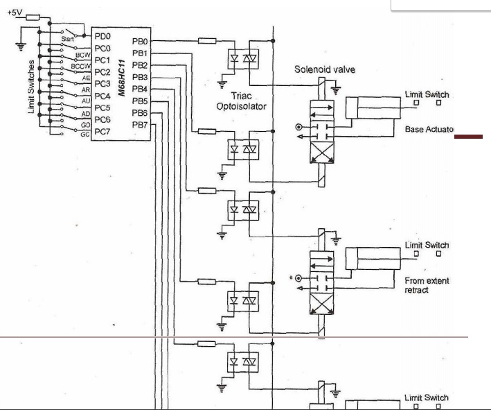
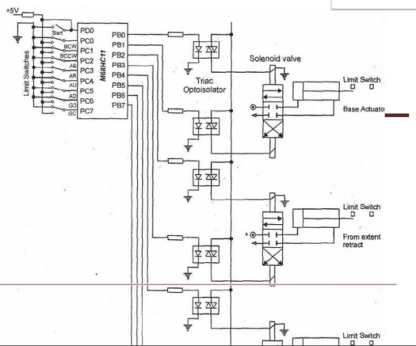
The micro controller used to control the solenoid values and
hence the movements of the robot unit. The type of microcontroller used in M68C11.
A
software program is used to control the robot.
Eight C port lies PC0 – PC7, are used to
sense the position of eight separate limit switches used for eight different
robotic movements.
Also one
line from port D is used to start or stop the robot operation.
The switch in its one position will provide +5V (a logic high
signal), to the corresponding port lines and the switch in another position
will provide 0V (a logic low
signal),
to the port lines.
So the two positions of a switch will provide either a logic
high or logic low to the corresponding PC0 – PC7, and PD,
lines.
Eight part B lines (PB0 – PB7) are used
to control eight different movement. These are Base CW, Base CEW, Arm extends,
Arm retract, Arm up, Arm down Gripper close and
Gripper
open of the robot.
PB0,
is connected to the Triacoptoisolator through a resistor.
TRIAC
isolator consists of LED and TRIAC.
For example, when the base has to rotate in clockwise
direction, a high signal is sent through line PB0
The diode is forward biased and the TRIAC optoisolation
operates, regulating the supply to the solenoid value which in turn operated
the piston rod of the pneumatic cylinder.
The base
clockwise continues the rotation till it reader the position of second limit
switch
Related Topics