Chapter: Transmission Lines and Waveguides : Waveguides and Cavity Resonators
Transverse Electromagnetic waves, Transverse Magnetic waves, Transverse Electric waves
Transverse Electromagnetic waves, Transverse Magnetic waves, Transverse Electric waves
Consider the propagation of an electromagnetic wave through a conducting medium which obeys Oh m's law:
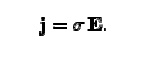
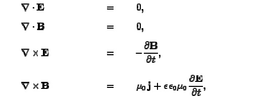
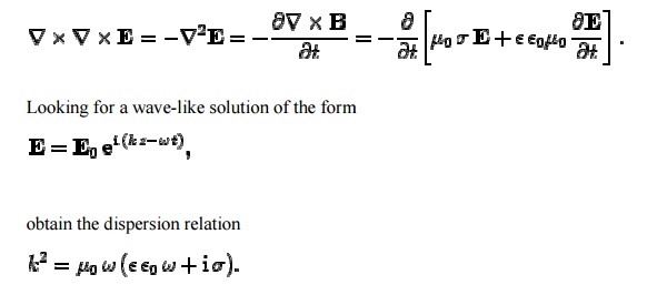
Here, Žā is the conductivity of the medium. Maxwell's equations for the wave take the form:
It can be seen that the skin-depth for a good conduc tor decreases with increasing wave
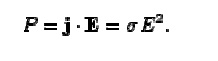
It can be seen that the skin-deepth for a good conductor decreases with increasing wave frequency. The fact that k,d=1 indicates that the wave only penetrates a few wave-lengths into the conductor before decaying away. Now the power per unit volume dissipate d via ohmic heating in a conducting medium takes the for m
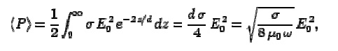
Consider an electro magnetic wave of the fo rm. The m ean power dissipated per unit area in the region z> 0 is written
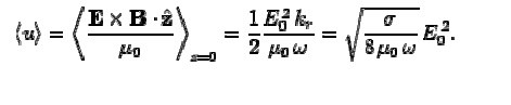
For a good conductor. Now, the mean electromagnetic power flux into the region z>0 takes the form
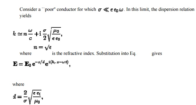
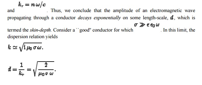
The amplitude of an electro magnetic wave propagating through a conductor decays exponentially on some length-scale, which is termed the skin-depth. The skin-depth for a poor conductor is independent of the frequency of the wave. For a poor conductor, indicating that the wave penetrates many wave-lengths into the conductor before decaying away.
WaveguideŌĆÖs equations:
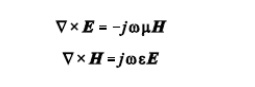
According to AmpereŌĆÖs law and FaradayŌĆÖs la w, we obtain
General Guided Wave Solutions:
General solutions to the fields associated with the waves that propagate on a guiding structure using MaxwellŌĆÖs equations.
Assume the following about the guiding structure:
(1) the guiding structure is infinitely long, oriented along the zaxis, and uniform along its length.
(2) the guiding structure is constructed from ideal materials (conductors are PEC and insulators are lossless).
(3) fields are time-harmonic. The fields of the guiding structure must satisfy the source free MaxwellŌĆÖs equations given by
For a wave propagating along the guiding structure in the z-direction, the associated electric and magnetic fields may be written as
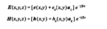
The vectors e(x,y) and h(x,y) represent the transverse field components of the wave while vectors ez(x,y)az and hz(x,y)az are the longitudinal components of the wave. By expanding the curl operator in rectangular coordinates, and noting that the derivatives of the transverse components with respect to z can be evaluated as
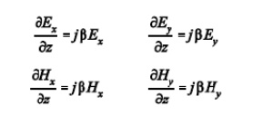
Equate the vector components on each side of the equation to write the six components of the electric and magnetic field as
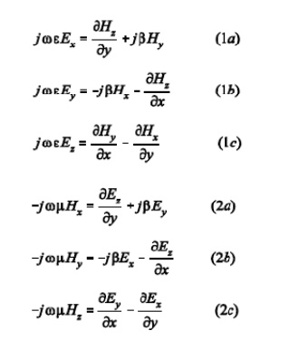
Equations (1) and (2) are valid for any wave (guided or unguided) propagating in the z-direction in a source-free region with a propagation constant of jâ. We may use Equations (1) and (2) to solve for the longitudinal field components in terms of the transverse field components.
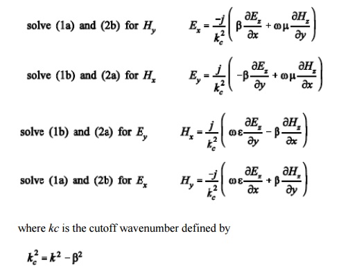
The cutoff wavenumber for the wave guiding structure is determined by the wavenumber of the insulating medium through which the wave propagates (k = ├╣ %├¼&├ź& ) and the propagation constant for the structure (j├ó). The equations for the transverse components of the fields are valid for all of the modes defined previously. These transverse field component equations can be specialized for each one of these guided structure modes.
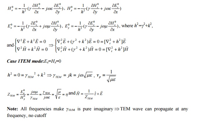
TEM Mode:
Using the general equations for the transverse fields of guided waves [Equation (3)], we see that the transverse fields of a TEM mode (defined by Ez = Hz = 0) are non-zero only when kc = 0. When the cutoff wavenumber of the TEM mode is zero, an indeterminant form of (0/0) results for each of the transverse field equations
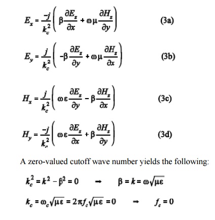
The first equation above shows that the phase constant â of the TEM mode on a guiding structure is equivalent to the phase constant of a plane wave propagating in a region characterized by the same medium between the conductors of the guiding structure. The second equation shows that the cutoff frequency of a TEM mode is 0 Hz. This means that TEM modes can be propagated at any non-zero frequency assuming the guiding structure can support a TEM mode.
Relationships between the transverse fields of the TEM mode can be determined by returning to the source-free MaxwellŌĆÖs equation results for guided waves [Equations (1) and (2)] and setting Ez = Hz = 0 and ├ó = k.
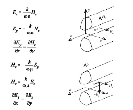
Note that the ratios of the TEM electric and magnetic field components define wave impedances which are equal to those of equivalent plane waves.
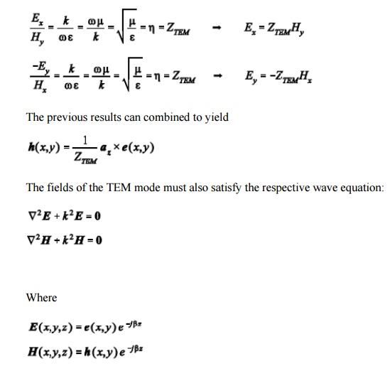
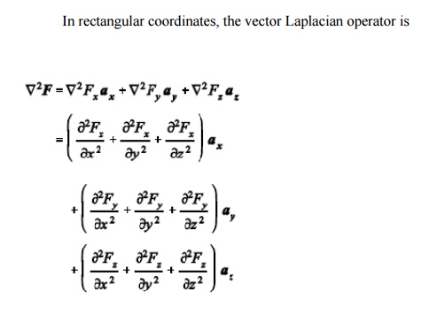
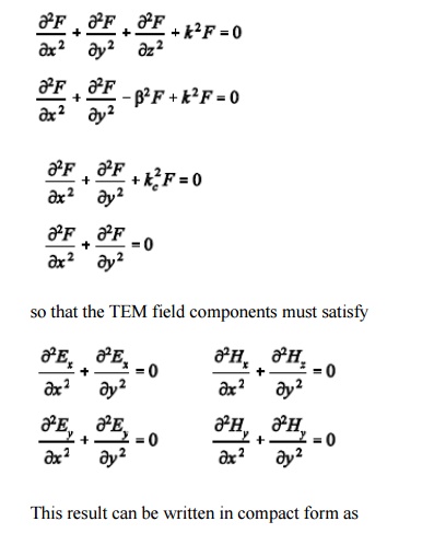
By separating the rectangular coordinate components in the wave equation, we find that each of the field components F 0 (Ex, Ey, Hx, Hy) must then satisfy the same equation [Helmholtz equation].
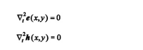
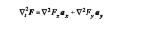
where Lt defines the transverse Laplacian operator which in rectangular 2 coordinates is
According to the previous result, the transverse fields of the TEM mode must satisfy LaplaceŌĆÖs equation with boundary conditions defined by the conductor geometry of the guiding structure, just like the static fields which would exist on the guiding structure for f = 0. Thus, the TEM transverse field vectors e( x,y) and h( x,y) are identical to the static fields for the transmission line. This allows us to solve for the static fields of a given guiding structure geometry (LaplaceŌĆÖs equation) to determine the fields of the TEM mode.
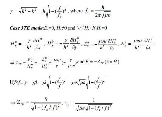
TE Modes:
The transverse fields of TE modes are found by simplifying the general guided wave equations in (3) with Ez = 0. The resulting transverse fields for TE modes are
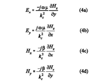
The cutoff wavenumber kc must be non-zero to yield bounded solutions for the transverse field components of TE modes. This means that we must operate the guiding structure above the corresponding cutoff frequency for the particular TE mode to propagate. Note that all of the transverse field components of the TE modes can be determined once the single longitudinal component (Hz) is found. The longitudinal field component Hz must satisfy the wave equation so that
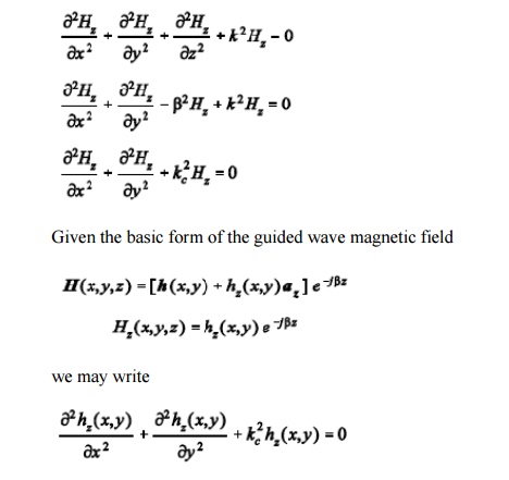
The equation above represents a reduced Helmholtz equation which can be solved for hz(x,y) based on the boundary conditions of the guiding structure geometry. Once hz(x,y) is found, the longitudinal magnetic field is known, and all of the transverse field components are found by evaluating the derivatives in Equation (4).
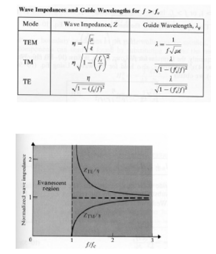
The wave impedance for TE modes is found from Equation (4):
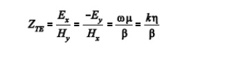
Note that the TE wave impedance is a function of frequency.
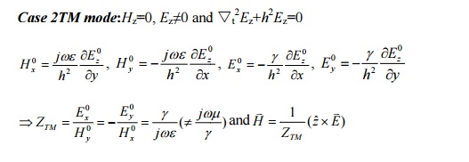
TM Modes
The transverse fields of TM modes are found by simplifying the general guided wave equations in (3) with Hz = 0. The resulting transverse fields for TM modes are
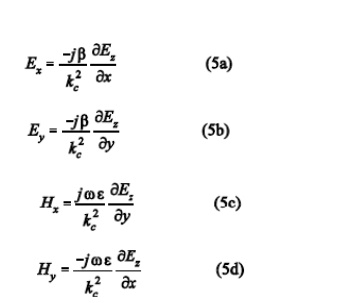
The cutoff wavenumber kc must also be non-zero to yield bounded solutions for the transverse field components of TM modes so that we must operate the guiding structure above the corresponding cutoff frequency for the particular TMmode to propagate. Note that all of the transverse field components of the TMmodes can be determined once the single longitudinal component (Ez) is found. The longitudinal field component Ez must satisfy the wave equation so that
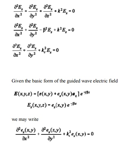
The equation above represents a reduced Helmholtz equation which can be solved for ez(x,y) based on the boundary conditions of the guiding structure geometry. Once ez(x,y) is found, the longitudinal magnetic field is known, and all of the transverse field components are found by evaluating the derivatives in Equation (5).
The wave impedance for TM modes is found from Equation (5):
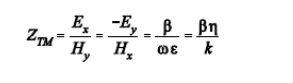
Note that the TM wave impedance is also a function of frequency.
Related Topics