Chapter: Mechanical : Design of Machine Elements : Design of Energy Storing Elements
Solved Problems: Design of Energy Storing Elements
A helical spring is made from a wire of 6 mm
diameter and has outside diameter of 75 mm. If the permissible shear stress is
350 MPa and modulus of rigidity 84 kN/mm2, find the axial load which the spring
can carry and the deflection per active turn. Solution.
Given :
d = 6 mm
; Do = 75 mm ;
= 350 MPa = 350 N/mm2 ;
G = 84
kN/mm2 = 84 × 103 N/mm2
We know
that mean diameter of the spring,
= Do – d
=75 – 6
=69 mm
Spring
index, C = D/d
= 69 / 6
=
11.5
Let W =
Axial load, and
δ/ n = Deflection per active turn.
1.
Neglecting the effect of curvature
We know
that the shear stress factor,
Ks = 1 + (1 / 2C)
= 1 + (1/ 2x11.5)
=1.043
Maximum
shear stress induced in the wire (τ),
= Ks (8WD / πd3)
=1.043 (8W x 69 / π x 63) W = 350 / 0.848
=412.7 N
We know
that deflection of the spring, δ = 8WD3n / Gd4
Deflection
per active turn,
δ/n = 8WD3 / Gd4
=9.96 mm
Considering
the effect of curvature
We know that Wahl’s stress factor,
= 4 ( 11 . 5)− 1 + 0. 615 4(11.5)−4
11.5
=
1.123
We also
know that the maximum shear stress induced in the wire (τ),
= K x (8WC / πd2) = 0.913 W
W = 350 / 0.913
=
383.4 N
Deflection
of the spring,
= 8WD3n / Gd4
Deflection
per active turn,
δ/n = 8WD3 / Gd4
=9.26 mm
Design a
helical spring for a spring loaded safety valve (Rams bottom safety valve) for
the following conditions. Diameter of valve seat = 65 mm ; Operating pressure =
0.7 N/mm2; Maximum pressure when the valve blows off freely = 0.75 N/mm2;
Maximum lift of the valve when the pressure rises from 0.7 to 0.75 N/mm2 = 3.5
mm: Maximum allowable stress = 550 MPa ;Modulus of rigidity = 84 kN/mm2; Spring
index = 6.
Solution.
Given :
D1 = 65
mm
p1 = 0.7
N/mm2
p2 = 0.75
N/mm2 ;
= 3.5 mm
δ = 550
MPa = 550 N/mm2
G = 84 C
= 6
kN/mm2 =
84
× 103
N/mm2
1. Mean
diameter of the spring coil
Let D = Mean diameter of the spring coil, and d =
Diameter of the spring wire.
Since the safety valve is a Rams bottom safety
valve, therefore the spring will be under tension. We know that initial tensile
force acting on the spring (i.e. before the valve lifts),
W1 = (π/4) x (D1)2 x p1
=(π/4) x (65)2 x 0.7
=2323 N
Maximum
tensile force acting on the spring (i.e. when the valve blows off freely), W2 =
(π/4) x (D1)2 x p2
=(π/4) x (65)2 x 0.75
=2489 N
Force
which produces the deflection of 3.5 mm,
= W2 – W1
=2489 – 2323
=166 N
Since the
diameter of the spring wire is obtained for the maximum spring load (W2),
therefore maximum twisting moment on the spring,
= W2 x D/2
=2489x 6 d / 2
=7467 d
We know
that maximum twisting moment (T ), 7467 d = (π/16) x τ x d3
=(π/16) x 550 x d3 d2 = 7467
/ 108
=69.14
d
= 8.3 mm
From
Table 23.2, we shall take a standard wire of size SWG 2/0 having diameter (d)
d
= 8.839 mm
Mean
diameter of the coil,
= 6 d
=6 × 8.839
=53.034 mm
Outside
diameter of the coil,
Do = D +
d
=53.034 +
8.839
=61.873 mm
Inside
diameter of the coil,
Di =
D – d
=53.034 – 8.839
=44.195 mm
Number of
turns of the coil
Let n =
Number of active turns of the coil. We know that the deflection of the spring
(δ),
3.5= 8WC3n
/ Gd
=8 x 166 x 63 x n / 84x103 x
8.839 n = 3.5 / 0.386
=9.06 say 10
For a
spring having loop on both ends, the total number of turns, n' = n + 1
=10 + 1
=11
Free
length of the spring
Taking
the least gap between the adjacent coils as 1 mm when the spring is in free
state, the free length of the tension spring,
LF = n.d + (n
– 1) 1
=10 × 8.839 + (10 – 1) 1
=97.39 mm
Pitch of
the coil
We know
that
Pitch of the coil =
Free length / n – 1
=97.39 / 10 – 1
=10.82 mm
Solution.
Given :
N = 300
r.p.m.
= 2 ×π x 300/60 = 31.42 rad/s ;
σt = 5.6
MPa = 5.6 × 10⁶ N/m2 ; ρ = 7200 kg/m3
Diameter
of the flywheel
Let D =
Diameter of the flywheel in metres.
We know
that peripheral velocity of the flywheel,
v = π
D N / 60
= π D ×300 / 60
= 15.71 D m/s
We also
know that hoop stress (σt ),
× 106
= ρ × v2
=7200 (15.71 D)2
=1.8 × 10⁶ D2
D2 = 5.6 × 10⁶ / 1.8 × 106
= 3.11
D = 1.764 m
Cross-section
of the flywheel
Let t = Thickness of the flywheel rim in
metres, and
b = Width
of the flywheel rim in metres = 4 t’
Cross-sectional
area of the rim, A = b × t
= 4 t × t
Now let
us find the maximum fluctuation of energy
Since the
scale of crank angle is 1 mm = 2.4º
= 2.4 × (π / 180)
= 0.042
rad,
The scale
of the turning moment is 1 mm = 650 N-m,
1 mm2 on
the turning moment diagram = 650 ×
0.042
= 27.3
N-m
Let the
total Energy at A = E. Therefore from Fig. 22.13, we find that
Energy at
B = E – 32
Energy at
C = E – 32 + 408 = E + 376
Energy at
D = E + 376 – 267 = E + 109
Energy at
E = E + 109 + 333 = E + 442
Energy at
F = E + 442 – 310 = E + 132
Energy at
G = E + 132 + 226 = E + 358
Energy at
H = E + 358 – 374 = E – 16
Energy at
I = E – 16 + 260 = E + 244
Energy at
J = E + 244 – 244 = E = Energy at A
From above, we see that the energy is maximum
at E and minimum at B.
Maximum energy =
E + 442
and minimum
energy = E – 32
We know
that maximum fluctuation of energy,
∆ E =
Maximum energy – Minimum energy = (E + 442) – (E – 32)
=474 mm2
=474 × 27.3
=12 940 N-m
Since the fluctuation of speed is ± 1.5% of the
mean speed, therefore total fluctuation of speed, ω1 – ω2 = 3% of mean speed
=
0.03 ω
coefficient
of fluctuation of speed,
CS = (ω1 − ω2)
/ ω
=
0.03
Let m =
Mass of the flywheel rim.
We know that maximum fluctuation of energy (∆E),
12940 = m.R2.ω2.CS
m x (1.764/2)2 x (31.42)2 x
0.03
=23 m
m = 12 940 /
23
=
563 kg
We also
know that mass of the flywheel rim (m),
= A × π D × ρ
=4 t2 × π × 1.764 × 7200
=159624 t2
t2 = 563 / 159624
=0.00353 t = 0.0594 m
=59.4 say 60 mm
= 4 t
=4 × 60
=240 mm
A punching
machine makes 25 working strokes per minute and is capable of punching 25 mm
diameter holes in 18 mm thick steel plates having an ultimate shear strength of
300 MPa. The punching operation takes place during 1/10 th of a revolution of
the crank shaft. Estimate the power needed for the driving motor, assuming a
mechanical efficiency of 95 percent. Determine suitable dimensions for the rim
cross-section of the flywheel, which is to revolve at 9 times the speed of the
crank shaft. The permissible coefficient of fluctuation of speed is 0.1. The
flywheel is to be made of cast iron having a working stress (tensile) of 6 MPa
and density of 7250 kg / m3. The diameter of the flywheel must not exceed 1.4 m
owing to space restrictions. The hub and the spokes may be assumed to provide 5%
of the rotational inertia of the wheel. Check for the centrifugal stress
induced in the rim.
Solution.
Given :
= 25 ;
d1 = 25 mm ;
t1 = 18 mm
;
τu = 300
MPa = 300 N/mm2 ;
ηm = 95%
= 0.95 ; CS = 0.1 ;
σt = 6
MPa = 6 N/mm2 ; ρ = 7250 kg/m3 ;
D = 1.4 m
= 0.7m
Power
needed for the driving motor
We know
that the area of plate sheared,
AS = d1 × t1
=π × 25 × 18
=1414 mm2
Maximum
shearing force required for punching,
FS = AS × τu
=1414 × 300
=424200 N
Energy
required per stroke = Average shear force × Thickness of plate
=½ x FS × t1
=½ × 424200 × 18
=3817.8 × 103 N-mm
Energy
required per min = Energy / stroke × No.
of working strokes / min
=3817.8 × 103 × 25
=95.45 × 10⁶ N-mm
=95 450 N-m
We know that
The power
needed for the driving motor = Energy required per min / (60 × ηm)
=95450 / (60 × 0.95)
=1675 W
Dimensions
for the rim cross-section
Considering
the cross-section of the rim as rectangular and assuming the width of rim equal
to twice the thickness of rim.
Let t =
Thickness of rim in metres, and
b = Width
of rim in metres = 2 t.
Cross-sectional
area of rim,
= b × t
=2 t × t
=2 t2
Maximum
fluctuation of energy, ∆ E = 9/10 × Energy/stroke
=9/10 × 3817.8 × 103
=3436 × 103 N-mm
=436 N-m
Let m =
Mass of the flywheel.
Since the hub and the spokes provide 5% of the
rotational inertia of the wheel, therefore the maximum fluctuation of energy
provided by the flywheel rim will be 95%.
Maximum fluctuation of energy provided by the rim,
(∆ E)rim = 0.95 × ∆ E
=0.95 × 3436
=3264 N-m
Since the
flywheel is to revolve at 9 times the speed of the crankshaft and there are 25
working strokes per minute, therefore mean speed of the flywheel,
= 9 × 25
=
225 r.p.m.
Mean
angular speed, ω = 2 π × 225 / 60
=
23.56 rad/s
We know that maximum fluctuation of energy (∆ E),
3264 = m.R2.ω2.CS
=m (0.7)2 (23.56)2 x 0.1
=27.2 m
= 3264 / 27.2
=
120 kg
= A × π D × ρ
=2 t2 × π × 1.4 × 7250
=63 782 t2
t2 = 120 / 63 782 = 0.001 88 or
t = 0.044 m
= 44 mm
= 2 t
= 2 × 44 = 88 mm
Check for
centrifugal stress
We know
that peripheral velocity of the rim,
= (π D N) / 60
=π ×1.4 ×225 / 60
=16.5 m/s
Centrifugal stress induced in the rim, σt = ρ.v2
=7250 (16.5)2
=1.97 × 10⁶ N/m2
=1.97 MPa
Since the
centrifugal stress induced in the rim is less than the permissible value (i.e.
6 MPa), therefore it is safe
A split
type flywheel has outside diameter of the rim 1.80 m, inside diameter 1.35 m
and the width 300 mm. the two halves of the wheel are connected by four bolts
through the hub and near the rim joining the split arms and also by four shrink
links on the rim. The speed is 250 r.p.m. and a turning moment of 15 kN-m is to
be transmitted by the rim. Determine:
The
diameter of the bolts at the hub and near the rim, σtb = 35 MPa.
The
cross-sectional dimensions of the rectangular shrink links at the rim, σtl = 40MPa; w = 1.25 h.
The
cross-sectional dimensions of the elliptical arms at the hub and rim if the
wheel has six arms, σta = 15
MPa, minor axis being 0.5 times the major axis and the diameter of shaft being
150 mm. Assume density of the material of the flywheel as 7200 kg / m3.
Solution
Given :
D0 = 1.8
m Di = 1.35 m
b = 300
mm = 0.3 m N = 250 r.p.m.
T = 15
kN-m = 15 000 N-m σtb = 35 MPa = 35 N/mm2 σtl = 40 MPa = 40 N/mm2 w = 1.25 h
n = 6
b1 = 0.5
a1
σta = 15
MPa = 15 N / mm2 d1 = 150 mm
= 7200 kg / m3.
Diameter
of the bolts at the hub and near the rim
Diameter
of the bolts at the hub and near the rim
Let dc =
Core diameter of the bolts in mm.
We know
that mean diameter of the rim,
D = (Do +
Di)/2
=(1.8 + 1.35) / 2
=1.575 m
Thickness
of the rim,
= (Do - Di)/2
=(1.8 - 1.35) / 2
=0.225 m
Peripheral
speed of the flywheel,
= (π D N) / 60
=π ×1.575 ×250 / 60
=20.6 m / s
We know
that centrifugal stress (or tensile stress) at the rim, σt = ρ × v2
=7200 (20.6)2
=3.1 × 10⁶ N/m2
=3.1 N/mm2
Cross-sectional
area of the rim,
= b × t
=0.3 × 0.225
=0.0675 m2
Maximum
tensile force acting on the rim
=σt × A
=3.1 × 106 × 0.0675
=209250N
……………………………………. (i)
We know that tensile strength of the four bolts
=(π/4) (dc)2 σtb× No. of bolts
=(π/4) (dc)2 x 35 x 4
=110(dc)2
………………………………………(ii)
Since the
bolts are made as strong as the rim joint, therefore from equations (i) and (ii), we have
(dc)2 = 209250 / 110
= 1903
dc
= 43.6 mm
The
standard size of the bolt is M 56 with dc = 48.65 mm.
2.
Cross-sectional dimensions of rectangular shrink links at the rim
Let h =
Depth of the link in mm, and
w = Width of the link in mm = 1.25 h
Cross-sectional area of each link,
Al = w × h
= 1.25 h2
mm2
We know
that
Maximum
tensile force on half the rim = 2 × σt for rim × Cross-sectional area of rim =
2 × 3.1 × 106 × 0.0675
= 418 500
N ……….……………………..(iii)
Tensile
strength of the four shrink links
=σtl × Al × 4
=40 × 1.25 h2 × 4
=200h2
………..……………………………..(iv)
h2 = 418500 / 200 = 2092.5
h
= 45.7 say 46 mm
and
w = 1.25 h
=1.25 × 46
=57.5 say 58 mm
Cross-sectional
dimensions of the elliptical arms
Let a1 =
Major axis,
b1 =
Minor axis = 0.5 a1 n = Number of arms = 6
Since the
diameter of shaft (d1) is 150 mm and the diameter of hub (d) is taken equal to
twice the diameter of shaft, therefore
d = 2 d1
=2 × 150
=300 mm = 0.3 m
We know
that maximum bending moment on arms at the hub end,
=(T/Dn) (D-d)
=(15000 / 1.575 × 6) (1.575 – 0.3)
=2024 N-m
=2024 × 103 N-mm
=(π / 32)× 0.5 a1 (a1)2
=0.05 (a1)3
We know
that bending stress for arms (σta),
= M / Z
=2024 x 103 / 0.05 (a1)3 (a1)3
= 40.5 × 10⁶ / 15
=2.7 × 10⁶
a1 = 139.3
say 140 mm
and
b1 = 0.5 a1
0.5 × 140 =70 mm
A punching
press pierces 35 holes per minute in a plate using 10 kN-m of energy per hole
during each revolution. Each piercing takes 40 per cent of the time needed to
make one revolution. The punch receives power through a gear reduction unit
which in turn is fed by a motor driven belt pulley 800 mm diameter and turning
at 210 r.p.m. Find the power of the electric motor if overall efficiency of the
transmission unit is 80 per cent. Design a cast iron flywheel to be used with
the punching machine for a coefficient of steadiness of 5, if the space
considerations limit the maximum diameter to 1.3 m.
Allowable
shear stress in the shaft material = 50 MPa Allowable tensile stress for cast
iron = 4 MPa Density of cast iron = 7200 kg / m3
Solution.
Given :
No. of
holes = 35 per min ;
Energy
per hole = 10 kN-m = 10 000 N-m ; d = 800 mm = 0.8 m ;
N = 210
r.p.m. ; η = 80% = 0.8 ;
1/CS = 5
or CS = 1/5 = 0.2 ; Dmax = 1.3 m ;
τ = 50
MPa = 50 N/mm2 ;
σt = 4
MPa = 4 N/mm2 ; ρ = 7200 kg / m3
Power of
the electric motor
We know
that energy used for piercing holes per minute
=No. of holes pierced × Energy used per hole
=35 × 10 000
=350 000 N-m / min
Power
needed for the electric motor, P =
Energy used per minute / (60 × η)
=350000 / (60 × 0.8)
=7292 W = 7.292 kW
Design
of cast iron flywheel
First of
all, let us find the maximum fluctuation of energy.
Since the
overall efficiency of the transmission unit is 80%, therefore total energy to
be supplied during each revolution,
ET = 10000/0.8
=
12 500 N-m
We know
that velocity of the belt,
= π d.N
= π × 0.8
× 210
= 528
m/min
Net
tension or pull acting on the belt = (Px 60) / v
=(7292 x 60) / 528
=828.6 N
Since
each piercing takes 40 per cent of the time needed to make one revolution,
therefore time required to punch a hole
=0.4 / 35
=0.0114 min
and the
distance moved by the belt during punching a hole
=Velocity of the belt × Time required to punch a hole
=528 × 0.0114
=6.03 m
Energy
supplied by the belt during punching a hole,
EB = Net
tension × Distance travelled by belt
=828.6 × 6.03
=4996 N-m
Thus
energy to be supplied by the flywheel for punching during each revolution or
maximum fluctuation of energy,
∇ E = ET – EB
=12 500 – 4996
=7504 N-m
1. Mass of
the flywheel
Let m =
Mass of the flywheel rim.
Since space considerations limit the maximum
diameter of the flywheel as 1.3 m ; therefore let us take the mean diameter of
the flywheel,
D = 1.2 m
or R = 0.6 m
We know
that angular velocity
= 2 π N / 60
=(2 x π x 210) / 60
=22 rad / s
We also
know that the maximum fluctuation of energy ( E), 7504 = m.R2. ω2.CS
=m x (0.6)2 x (22)2 x 0.2
=34.85 m
= 7504 / 34.85
=
215.3 kg
Cross-sectional
dimensions of the flywheel rim
Let t =
Thickness of the flywheel rim in metres, and
b = Width
of the flywheel rim in metres = 2 t
Cross-sectional
area of the rim,
= b × t
=2 t × t
=2 t2
We know
that mass of the flywheel rim (m),
= A × πD × ρ
=2 t2 × π × 1.2 × 7200
=54.3 × 10³ t2
t2 = 215.3 / 54.3 × 103 =
0.00396
t = 0.063
say 0.065 m = 65 mm
= 2 t
=2 × 65
=130 mm
Diameter
and length of hub
Let d = Diameter of the hub,
d1 =
Diameter of the shaft, and l = Length of the hub.
First of
all, let us find the diameter of the shaft (d1). We know that the mean torque
transmitted by the shaft,
Tmean =
(P x 60) / 2 π N
=(7292 x 60) / 2π x 210
=331.5 N-m
Assuming
that the maximum torque transmitted by the shaft is twice the mean torque, therefore
maximum torque transmitted by the shaft,
Tmax = 2 × Tmean
=2 × 331.5
=663 N-m
=663 × 103 N-mm
We know that maximum torque transmitted by the
shaft (Tmax), 663 × 103
=(π/16) × τ x (d1)3
=(π/16) × 50 (d1)3
=9.82 (d1)3
(d1)3 = 663 × 103 / 9.82 = 67.5 × 10³
d1 = 40.7 say
45 mm
The
diameter of the hub (d ) is made equal to twice the diameter of the shaft (d1)
and length of hub ( l ) is equal to the width of the rim (b).
= 2 d1
=2 × 45
90 mm = 0.09 m l = b = 130 mm
Cross-sectional
dimensions of the elliptical cast iron arms
Let a1 = Major axis,
b1 =
Minor axis = 0.5 a1 n = Number of arms = 6
We know
that the maximum bending moment in the arm at the hub end, which is assumed as
cantilever is given by
= (T / R n) (R – r)
=(T / D n) (D – r)
=(663 / 1.2 x 6 ) (1.2 – 0.09) N-m
=102.2 N-m
=102200 N-mm
Section
modulus for the cross-section of the arms,
= (π / 32) × b1 (a1)2
=(π / 32) × 0.5 a1 (a1)2
=0.05 (a1)3
We know
that bending stress (σt),
= M / Z
=102200 / 0.05 (a1)3 (a1)3 =
2044 × 103 / 4
=511 × 103
a1 = 80 mm
and b1 = 0.5 a1
= 0.5 ×
80
= 40 mm
5. Dimensions of key
The
standard dimensions of rectangular sunk key for a shaft of diameter 45 mm are
as follows:
Width of
key, w = 16 mm
Thickness
of key t = 10 mm
The
length of key (L) is obtained by considering the failure of key in shearing.
We know
that maximum torque transmitted by the shaft (Tmax),
663 × 103 = L × w × τ × (d1/2)
= L × 16 × 50 × (45 / 2)
= 18 × 103 L
L = 663 × 103/18 × 103
= 36.8
say 38 mm
L = 663 ×
103/18 × 103
= 36.8 say
38 mm
Let us
now check the total stress in the rim which should not be greater than 4 MPa.
We know that the velocity of the rim,
= π d.N / 60
=π 1.2 x 210 / 60
=13.2 m/s
Total
stress in the rim,
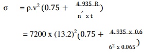
=1 .25 × 106 (0.75 + 1.26)
=2 .5 × 106 N/m2
=2 .5 MPa
Since it
is less than 4 MPa, there fore the design is safe.
A shaft
fitted with a flywhe el rotates at 250 r.p.m. and drives a machine . The torque
of machine varies in a cyclic anner over a period of 3 revolutions. The torque
rises from 750 N-m to 3000 N-m uniformly during 1 / 2 revolution and remains
constant for the following revolution. It the n falls uniformly to 750 N-m
during the next 1 / 2 revolution and remains constant for o ne revolution, the
cycle being repeated there after. Determine the power required to drive the
machine. If the total fluctuation of speed is not to exceed 3% of the mean
speed, determine a suitable diameter and cross-sectio n of the flywheel rim.
The width of the rim i s to be 4 times the thickness and the safe cen rifugal
stress is 6 MPa. The material density may be assumed as 7200 kg / m3.
Given :
N = 250 r.p.m.
ω = 2 π ×
250 / 60 = 26.2 rad/s ; ω1 – ω2 = 3% ω o r
=(ω1 –
ω2) / ω = CS = 3% = 0.03 ; σt = 6 MPa = 6 × 10⁶ N/m2 ;
ρ = 7200
kg / m3
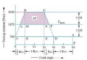
We know
that the torque required for one complete cycle
Area of figure OABCDEF
Area OA EF + Area ABG + Area BCHG + Area CDH
OF × O A + ½ × AG × BG + GH × CH + ½ × HD × CH
6 π × 750 + ½ × π (3000 – 750) + 2π (3000 – 750) +
½ × (3000 – 750)
=4500 π + 1125 π + 4500 π + 1125 π
= 11 250 π N-m
…………………… ………...(i)
If Tmean
is the mean torque in N-m, then
Torque
required for one complete cycle = Tmean × 6 π N-m …………… ………....(ii)
From
equations (i) and (ii),
Tmean = 11250 π / 6 π
= 1875 N-m
We know
that power required to drive the machine,
= Tmean × ω
=1875 × 26.2
=49125 W
=49.125 kW
Diameter
of the flywheel
Let D =
Diameter of the flywheel in metres, and
v =
Peripheral velocity of the flywheel in m/s.
We know that the centrifugal stress (σt), 6 ×106
= ρ × v2
= 7200 ×
v2
v2 =
6 × 10⁶ / 7200
= 833.3
v = 28.87 m/s
We also
know that peripheral velocity of the flywheel (v),
= π D N / 60
=π D × 250 / 60
=13.1 D
D = 28.87 /
13.1
= 2.2 m Cross-section of the flywheel rim
Let t = Thickness of the flywheel rim in metres,
and b = Width of the flywheel rim in metres = 4 t
Cross-sectional
area of the flywheel rim,
= b × t
4 t × t
4 t2 m2
First of
all, let us find the maximum fluctuation of energy (∆ E) and mass of the
flywheel rim (m). In order to find ∆E, we shall calculate the values of LM and
NP. From similar triangles ABG and BLM,
LM / AG = BM / BG
LM / π = (3000 – 1857) / (3000 – 750)
= 0.5
LM = 0.5 π
Now from
similar triangles CHD and CNP,
NP / HD = CN / CH
NP / π = = (3000 – 1857) / (3000 – 750)
= 0.5
NP = 0.5 π
BM = CN =
3000 – 1875
=
1125 N-m
Since the
area above the mean torque line represents the maximum fluctuation of energy,
therefore maximum fluctuation of energy,
E = Area
LBCP = Area LBM + Area MBCN + Area PNC
½ × LM × BM + MN × BM + ½ × NP × CN
½ × 0.5 π × 1125 + 2 π × 1125 + ½ × 0.5 π × 1125
=8837 N-m
We know
that maximum fluctuation of energy (∆E), 8837 = m.R2.ω2.CS
=m (26.2)2 0.03
=24.9 m
= 8837 / 24.9
=355 kg
We also
know that mass of the flywheel rim (m),
= A × π D × ρ
=4 t2 × π × 2.2 × 7200
=199 077 t2
t2 =
355 / 199077
=0.00178 or t = 0.042 m
=42 say 45 mm
And b = 4 t
= 4 × 45 = 180 mm
Related Topics