Chapter: Optical Communication and Networking : Introduction
Single mode fiber
Single-mode fiber
The advantage of the propagation of a single mode within an optical fiber is that the signal dispersion caused by the delay differences between different modes in a multimode fiber may be avoided. Multimode step index fibers do not lend themselves to the propagation of a single mode due to the difficulties of maintaining single-mode operation within the fiber when mode conversion (i.e. coupling) to other guided modes takes place at both input mismatches and fiber imperfections.
Hence, for the transmission of a single mode the fiber must be designed to allow propagation of only one mode, while all other modes are attenuated by leakage or absorption. Following the preceding discussion of multimode fibers, this may be achieved through choice of a suitable normalized frequency for the fiber. For single-mode operation, only the fundamental LP01 mode can exist. Hence the limit of single-mode operation depends on the lower limit of guided propagation for the LP11 mode. The cutoff normalized frequency for the LP11 mode in step index fibers occurs at Vc = 2.405. Thus single-mode propagation of the LP01 mode in step index fibers is possible over the range:

as there is no cutoff for the fundamental mode. It must be noted that there are in fact two modes with orthogonal polarization over this range, and the term single-mode applies to propagation of light of a particular polarization. Also, it is apparent that the normalized frequency for the fiber may be adjusted to within the range given in Eq. (1.51) by reduction of the core radius.
1. Cutoff wavelength
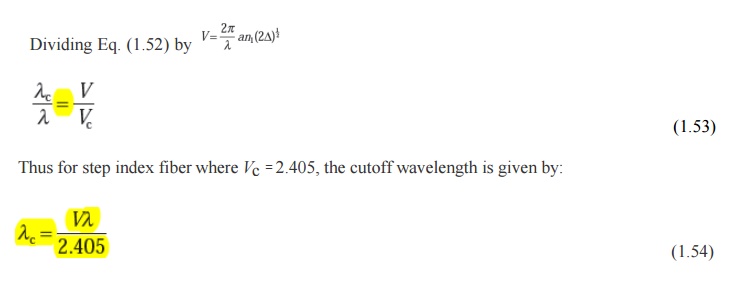
It may be noted that single-mode operation only occurs above a theoretical cutoff wavelength λc given by:

whereVc is the cutoff normalized frequency. Hence λc is the wavelength above which a particular fiber becomes single-moded.
An effective cutoff wavelength has been defined by the ITU-T which is obtained from a 2 m length of fiber containing a single 14 cm radius loop. This definition was produced because the first higher order LP11 mode is strongly affected by fiber length and curvature near cutoff. Recommended cutoff wavelength values for primary coated fiber range from 1.1 to 1.28 µm for single-mode fiber designed for operation in the 1.3µm wavelength region in order to avoid modal noise and dispersion problems. Moreover, practical transmission systems are generally operated close to the effective cutoff wave- length in order to enhance the fundamental mode confinement, but sufficiently distant from cutoff so that no power is transmitted in the second-order LP11 mode.
2. Mode-field diameter and spot size
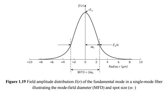
Many properties of the fundamental mode are determined by the radial extent of its electromagnetic field including losses at launching and jointing, micro bend losses, waveguide dispersion and the width of the radiation pattern. Therefore, the MFD is an important parameter for characterizing single-mode fiber properties which takes into account the wavelength-dependent field penetration into the fiber cladding. In this context it is a better measure of the functional properties of single-mode fiber than the core diameter. For step index and graded (near parabolic profile) single-mode fibers operating near the cutoff wavelength λc, the field is well approximated by a Gaussian distribution. In this case the MFD is generally taken as the distance between the opposite 1/e = 0.37 field amplitude points and the power 1/e2 = 0.135 points in relation to the corresponding values on the fiber axis.
Another parameter which is directly related to the MFD of a single-mode fiber is the spot size (or mode-field radius) ω0. Hence MFD = 2ω0, where ω0is the nominal half width of the input excitation.
The MFD can therefore be regarded as the single- mode analog of the fiber core diameter in multimode fibers. However, for many refractive index profiles and at typical operating wavelengths the MFD is slightly larger than the single-mode fiber core diameter.
Often, for real fibers and those with arbitrary refractive index profiles, the radial field distribution is not strictly Gaussian and hence alternative techniques have been proposed. However, the problem of defining the MFD and spot size for non-Gaussian field dis- tributions is a difficult one and at least eight definitions exist.
3. Effective refractive index
The rate of change of phase of the fundamental LP01 mode propagating along a straight fiber is determined by the phase propagation constant . It is directly related to the wavelength of the LP01 mode λ01 by the factor 2π, since β gives the increase in phase angle per unit length. Hence:
Moreover, it is convenient to define an effective refractive index for single-mode fiber, sometimes referred to as a phase index or normalized phase change coefficient neff, by the ratio of the propagation constant of the fundamental mode to that of the vacuum propagation constant:

Hence, the wavelength of the fundamental mode λ01 is smaller than the vacuum wave-length λ by the factor 1/neff where:
It should be noted that the fundamental mode propagates in a medium with a refractive index n(r) which is dependent on the distance r from the fiber axis. The effective refractive index cantherefore be considered as an average over the refractive index of this medium.
Within a normally clad fiber, not depressed-cladded fibers, at long wavelengths (i.e. small V values) the MFD is large compared to the core diameter and hence the electric field extends farinto the cladding region. In this case the propagation constant β will be approximately equal to n2k (i.e. the cladding wave number) and the effective index will be similar to the refractive indexof the cladding n2. Physically, most of the power is transmitted in the cladding material.
At short wavelengths, however, the field is concentrated in the core region and the propagation constant β approximates to the maximum wave numbernlk. Following this discussion, and as indicated previously, then the propagation constant in single-mode fiber varies over the interval n2k< β <n1k. Hence, the effective refractive index will vary over the range n2<neff<n1. In addition, a relationship between the effective refractive index and the normalized propagation constant b defined as:
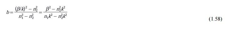
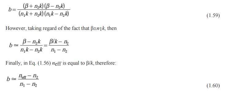
may be obtained. Making use of the mathematical relation A2 − B2 = (A + B)(A − B), Eq. (1.58) can be written in the form:
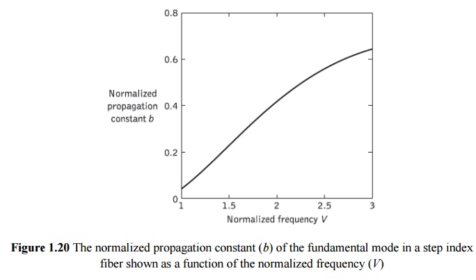
The dimensionless parameter b which varies between 0 and 1 is particularly useful in the theory of single-mode fibers because the relative refractive index difference is very small, giving only a small range for β. Moreover, it allows a simple graphical representation of results to be presented as illustrated by the characteristic shown in Figure 2.32 of the normalized phase constant of β as a function of normalized frequency V in a step index fiber.* It should also be noted that b(V) is a universal function which does not depend explicitly on other fiber parameters.
4. Group delay and mode delay factor
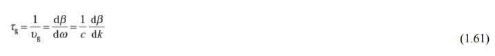
The transit time or group delay τg for a light pulse propagating along a unit length of fiber is the inverse of the group velocity υg . Hence:
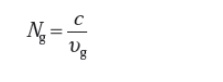
The group index of a uniform plane wave propagating in a homogeneous medium has been determined as:
However, for a single-mode fiber, it is usual to define an effective group index* Nge By:
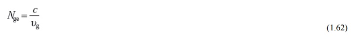
Where υg is considered to be the group velocity of the fundamental fiber mode. Hence, the specific group delay of the fundamental fiber mode becomes:

Moreover, the effective group index may be written in terms of the effective refractive index neff defined in Eq. (1.56) as:
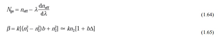
Furthermore, approximating the relative refractive index difference as (n1 − n2)/n2, for a weakly guiding fiber where Δ<<1, we can use the approximation :
Where Ng1 and Ng2 are the group indices for the fiber core and cladding regions respectively. Substituting Eq. (1.65) for β into Eq. (1.67) and using the approximate expression given in Eq. (1.66), we obtain the group delay per unit distance as:
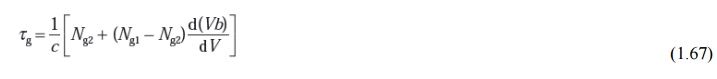
The dispersive properties of the fiber core and the cladding are often about the same and therefore the wavelength dependence of can be ignored. Hence the group delay can be written as:
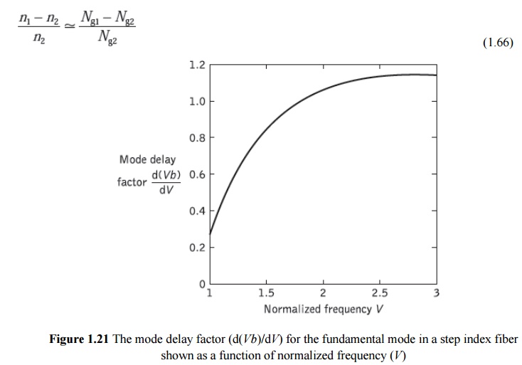
The initial term in Eq. (1.68) gives the dependence of the group delay on wavelength caused when a uniform plane wave is propagating in an infinitely extended medium with a refractive index which is equivalent to that of the fiber cladding. However, the second term results from the waveguiding properties of the fiber only and is determined by the mode delay factor d(Vb)/dV, which describes the change in group delay caused by the changes in power distribution between the fiber core and cladding. The mode delay factor [Ref. 50] is a further universal parameter which plays a major part in the theory of single- mode fibers. Its variation with normalized frequency for the fundamental mode in a step index fiber is shown in Figure 1.21.
5. The Gaussian approximation
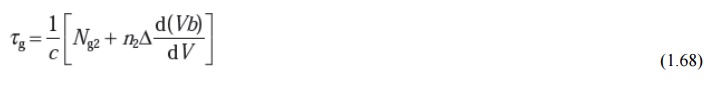
The field shape of the fundamental guided mode within a single-mode step index fiber for two values of normalized frequency is displayed in Figure 1.22.
As may be expected, considering the discussion in Section 2.4.1, it has the form of a Bessel function (J0(r)) in the core region matched to a modified Bessel function (K0(r)) in the cladding. Depending on the value of the normalized frequency, a significant proportion of the modal power is propagated in the cladding region, as mentioned earlier. Hence, even at the cutoff value (i.e. Vc) only about 80% of the power propagates within the fiber core.
It may be observed from Figure 1.22 that the shape of the fundamental LP01 mode is similar to a Gaussian shape, which allows an approximation of the exact field distribution by a Gaussian function.* The approximation may be investigated by writing the scalar wave equation in the form:

where k is the propagation vector defined in Eq. (1.33) and n(x, y) is the refractive index of the fiber, which does not generally depend on z, the coordinate along the fiber axis. It should be noted that the time dependence exp(jωt) has been omitted from the scalar wave equation to give the reduced wave equation† in Eq. (1.69). This representation is valid since the guided modes of a fiber with a small refractive index difference have one predominant transverse field component, for example Ey. By contrast
Ex and the longitudinal component are very much smaller.
The field of the fundamental guided mode may therefore be considered as a scalar quantity and need not be described by the full set of Maxwell’s equations. Hence Eq. (1.69) may be written as:

where φ represents the dominant transverse electric field component.
The near-Gaussian shape of the predominant transverse field component of the funda- mental mode has been demonstrated for fibers with a wide range of refractive index distributions. This proves to be the case not only for the LP01 mode of the step index fiber, but also for the modes with fibers displaying arbitrary graded refractive index distributions.
6. Equivalent step index method
Another strategy to obtain approximate values for the cutoff wavelength and spot size in graded index single-mode fibers (or arbitrary refractive index profile fibers) is to define an equivalent step index (ESI) fiber on which to model the fiber to be investigated. Various methods have been proposed in the literature which commence from the observation that the fields in the core regions of graded index fibers often appear similar to the fields within step index fibers. Hence, as step index fiber characteristics are well known, it is convenient to replace the exact methods for graded index single-mode fibers by approximate techniques based on step index fibers. In addition, such ESI methods allow the propagation characteristics of single-mode fibers to be represented by a few parameters.
Several different suggestions have been advanced for the choice of the core radius aESI, and the relative index difference ESI, of the ESI fiber which lead to good approximations for the spot size (and hence joint and bend losses) for the actual graded index fiber. They are all conceptually related to the Gaussian approximation in that they utilize the close resemblance of the field distribution of the LP01 mode to the Gaussian distribution within single-mode fiber.
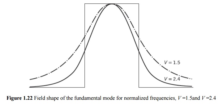
An early proposal for the ESI method involved transformation of the basic fiber parameters following/:
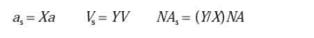
where the subscript s is for the ESI fiber and X, Y are constants which must be determined. However, these ESI fiber representations are only valid for a particular value of normalized frequency V and hence there is a different X, Y pair for each wavelength differences. Figure 1.23 compares the refractive index profiles and the electric field distri- butions for two graded index fibres (α = 2, 4) and their ESI fibers. It may be observed that their fields differ slightly only near the axis.
Related Topics