Chapter: Fundamentals of Database Systems : Conceptual Modeling and Database Design : Relational Database Design by ER- and EER-to-Relational Mapping
Relational Database Design Using ER-to-Relational Mapping
Relational Database Design Using ER-to-Relational Mapping
1. ER-to-Relational
Mapping Algorithm
In this
section we describe the steps of an algorithm for ER-to-relational mapping. We
use the COMPANY database example to illustrate
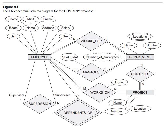
the mapping procedure. The COMPANY ER schema
is shown again in Figure 9.1, and the corresponding COMPANY relational database schema is
shown in Figure 9.2 to illustrate the
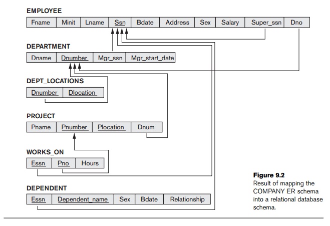
mapping
steps. We assume that the mapping will create tables with simple single-valued
attributes. The relational model constraints defined in Chapter 3, which
include primary keys, unique keys (if any), and referential integrity
constraints on the rela-tions, will also be specified in the mapping results.
Step 1: Mapping of Regular Entity Types. For each
regular (strong) entity type
E in the ER schema, create a
relation R that includes all the
simple attributes of E. Include only the simple component
attributes of a composite attribute. Choose one of the key attributes of E as the primary key for R. If the chosen key of E is a com-posite, then the set of
simple attributes that form it will together form the primary key of R.
If
multiple keys were identified for E
during the conceptual design, the information describing the attributes that
form each additional key is kept in order to specify secondary (unique) keys of
relation R. Knowledge about keys is
also kept for index-ing purposes and other types of analyses.
In our
example, we create the relations EMPLOYEE, DEPARTMENT, and PROJECT in Figure 9.2 to correspond to
the regular entity types EMPLOYEE, DEPARTMENT, and PROJECT in Figure 9.1. The foreign key
and relationship attributes, if any, are
not
included yet; they will be added during subsequent steps. These include the
attributes Super_ssn and Dno of EMPLOYEE, Mgr_ssn and Mgr_start_date of DEPARTMENT, and Dnum of PROJECT. In our example, we choose Ssn, Dnumber, and Pnumber as primary keys for the
relations EMPLOYEE, DEPARTMENT, and PROJECT, respectively. Knowledge that Dname of DEPARTMENT and Pname of PROJECT are secondary keys is kept for
possible use later in the design.
The
relations that are created from the mapping of entity types are sometimes
called entity relations because each
tuple represents an entity instance. The result after this mapping step is shown in Figure 9.3(a).
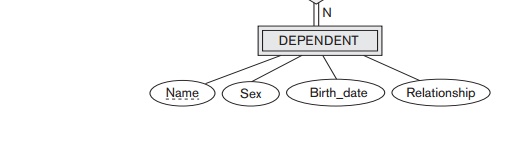
Step 2: Mapping of Weak Entity Types. For each
weak entity type W
in the ER schema with owner entity type E, create a relation R and include all simple attrib-utes (or
simple components of composite attributes) of W as attributes of R. In
addition, include as foreign key attributes of R, the primary key attribute(s) of the relation(s) that correspond
to the owner entity type(s); this takes care of mapping the identifying
relationship type of W. The primary
key of R is the combination of the
primary key(s) of the owner(s) and the partial key of the weak entity type W, if any.
If there
is a weak entity type E2
whose owner is also a weak entity type E1,
then E1 should be mapped
before E2 to determine its
primary key first.
In our
example, we create the relation DEPENDENT in this
step to correspond to the weak entity type DEPENDENT (see
Figure 9.3(b)). We include the primary key Ssn of the EMPLOYEE relation—which corresponds to
the owner entity type—as a for-eign key attribute of DEPENDENT; we rename it Essn, although this is not necessary.
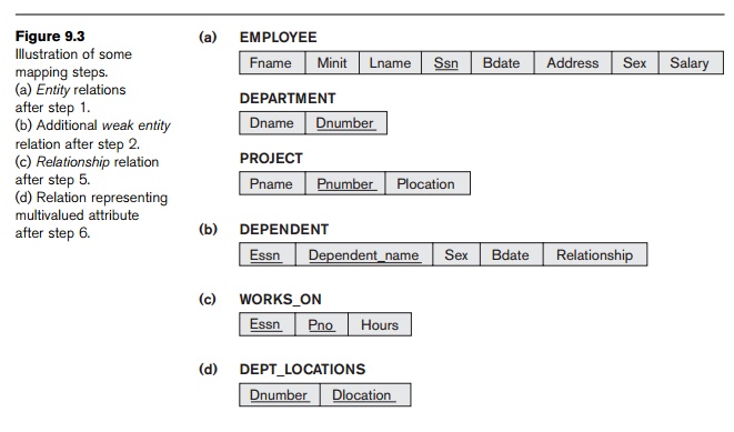
The
primary key of the DEPENDENT relation
is the combination {Essn, Dependent_name}, because Dependent_name (also renamed from Name in Figure 9.1) is the partial key of DEPENDENT.
It is
common to choose the propagate (CASCADE) option
for the referential triggered action (see Section 4.2) on the foreign key in
the relation corresponding to the weak entity type, since a weak entity has an
existence dependency on its owner entity. This can be used for both ON UPDATE and ON DELETE.
Step 3: Mapping of Binary 1:1 Relationship
Types. For each
binary 1:1 relationship type R in
the ER schema, identify the relations S
and T that correspond to the entity
types participating in R. There are
three possible approaches: (1) the foreign key approach, (2) the merged
relationship approach, and (3) the cross-reference or relationship relation
approach. The first approach is the most useful and should be followed unless
special conditions exist, as we discuss below.
Foreign
key approach: Choose one of the relations—S, say—and include as a
foreign key in S the primary key of T. It is better to choose an entity type
with total participation in R in the role of S. Include all the simple attributes (or simple components of
composite attributes) of the 1:1 relationship type R as attributes of S.
In our
example, we map the 1:1 relationship type MANAGES from
Figure 9.1 by choosing the participating entity type DEPARTMENT to serve in the role of S because its participation in the MANAGES relationship type is total
(every department has a manager). We include the primary key of the EMPLOYEE relation as foreign key in the DEPARTMENT relation and rename it Mgr_ssn. We also include the simple attribute Start_date of the MANAGES
relationship type in the DEPARTMENT relation
and rename it Mgr_start_date (see
Figure 9.2).
Note that
it is possible to include the primary key of S as a foreign key in T
instead. In our example, this amounts to having a foreign key attribute, say Department_managed in the EMPLOYEE relation, but it will have a NULL value for employee tuples who do not
manage a department. If only 2 percent of employees manage a department, then
98 percent of the foreign keys would be NULL in this
case. Another possibility is to have foreign keys in both relations S and T redundantly, but this creates redundancy and incurs a penalty for
consistency maintenance.
Merged
relation approach: An alternative mapping of a 1:1 relationship type is to merge the two entity types
and the relationship into a single rela-tion. This is possible when both participations are total, as this
would indicate that the two tables will have the exact same number of tuples at
all times.
Cross-reference or relationship relation approach: The third
option is to set up a third relation
R for the purpose of
cross-referencing the primary keys of the two relations S and T representing the
entity types. As we will see, this approach is required for binary M:N
relationships. The relation R is
called a relationship relation (or
sometimes a lookup table), because
each tuple in R represents a
relationship instance that relates one tuple from S with one tuple from T.
The relation R will include the
primary key attributes of S and T as foreign keys to S and T. The primary key of R
will be one of the two foreign keys, and the other foreign key will be a unique
key of R. The drawback is having an
extra relation, and requiring an extra join operation when combining related
tuples from the tables.
Step 4: Mapping of Binary 1:N Relationship
Types. For each
regular binary 1:N
relationship type R, identify the relation
S that represents the participating
entity type at the N-side of the
relationship type. Include as foreign key in S the primary key of the relation T that represents the other entity type participating in R; we do this because each entity
instance on the N-side is related to at most one entity instance on the 1-side
of the relationship type. Include any simple attributes (or simple compo-nents
of composite attributes) of the 1:N relationship type as attributes of S.
In our
example, we now map the 1:N relationship types WORKS_FOR, CONTROLS, and SUPERVISION from Figure 9.1. For WORKS_FOR we include the primary key Dnumber of the DEPARTMENT relation as foreign key in the EMPLOYEE relation and call it Dno. For SUPERVISION we include the primary key of
the EMPLOYEE relation as foreign key in the EMPLOYEE relation itself—because the
relationship is recur-sive—and call it Super_ssn. The CONTROLS relationship is mapped to the
foreign key attribute Dnum of PROJECT, which references the primary
key Dnumber of the DEPARTMENT relation. These foreign keys are
shown in Figure 9.2.
An
alternative approach is to use the relationship
relation (cross-reference) option as in the third option for binary 1:1
relationships. We create a separate relation R whose attributes are the primary keys of S and T, which will also
be foreign keys to S and T. The primary key of R is the same as the primary key of S. This option can be used if few tuples in S
participate in the relationship to avoid excessive NULL val-ues in the foreign key.
Step 5: Mapping of Binary M:N Relationship
Types. For each
binary M:N relationship
type R, create a new relation S to represent R. Include as foreign key attributes in S the primary keys of the relations that represent the
participating entity types; their combination
will form the primary key of S. Also
include any sim-ple attributes of the M:N relationship type (or simple
components of composite attributes) as attributes of S. Notice that we cannot represent an M:N relationship type by a
single foreign key attribute in one of the participating relations (as we did
for 1:1 or 1:N relationship types) because of the M:N cardinality ratio; we
must cre-ate a separate relationship
relation S.
In our
example, we map the M:N relationship type WORKS_ON from Figure
9.1 by creating the relation WORKS_ON in
Figure 9.2. We include the primary keys of the PROJECT and EMPLOYEE relations
as foreign keys in WORKS_ON and
rename them Pno and Essn, respectively. We also include
an attribute Hours in WORKS_ON to represent the Hours attribute of the relationship
type. The primary key of the WORKS_ON relation
is the combination of the foreign key attributes {Essn, Pno}. This relationship relation is shown in
Figure 9.3(c).
The
propagate (CASCADE) option
for the referential triggered action (see Section 4.2) should be specified on
the foreign keys in the relation corresponding to the relationship R, since each relationship instance has
an existence dependency on each of the entities it relates. This can be used
for both ON UPDATE and ON DELETE.
Notice
that we can always map 1:1 or 1:N relationships in a manner similar to M:N
relationships by using the cross-reference (relationship relation) approach, as
we discussed earlier. This alternative is particularly useful when few relationship
instances exist, in order to avoid NULL values
in foreign keys. In this case, the primary key of the relationship relation
will be only one of the foreign keys
that refer-ence the participating entity relations. For a 1:N relationship, the
primary key of the relationship relation will be the foreign key that
references the entity relation on the N-side. For a 1:1 relationship, either
foreign key can be used as the primary key of the relationship relation.
Step 6: Mapping of Multivalued Attributes. For each
multivalued attribute A, create a
new relation R. This relation R will include an attribute
corresponding to A, plus the primary
key attribute K—as a foreign key in R—of the relation that represents the
entity type or relationship type that has A
as a multivalued attribute. The primary key of R is the combination of A
and K. If the multivalued attribute
is composite, we include its simple components.
In our
example, we create a relation DEPT_LOCATIONS (see
Figure 9.3(d)). The attribute Dlocation
represents the multivalued attribute LOCATIONS of DEPARTMENT, while Dnumber—as foreign key—represents the
primary key of the DEPARTMENT relation.
The primary key of DEPT_LOCATIONS
is the
combination of {Dnumber, Dlocation}. A separate tuple will exist in DEPT_LOCATIONS for each loca-tion that a
department has.
The
propagate (CASCADE) option
for the referential triggered action (see Section 4.2) should be specified on
the foreign key in the relation R
corresponding to the multivalued attribute for both ON UPDATE and ON DELETE. We should also note that the
key of R when mapping a composite,
multivalued attribute requires some analysis of the meaning of the component
attributes. In some cases, when a multi-valued attribute is composite, only
some of the component attributes are required to be part of the key of R; these attributes are similar to a
partial key of a weak entity type that corresponds to the multivalued attribute
(see Section 7.5).
Figure
9.2 shows the COMPANY
relational database schema obtained with steps 1 through 6, and Figure 3.6
shows a sample database state. Notice that we did not yet discuss the mapping
of n-ary relationship types (n > 2) because none exist in Figure
9.1; these are mapped in a similar way to M:N relationship types by including
the following additional step in the mapping algorithm.
Step 7: Mapping of N-ary Relationship Types. For each n-ary
relationship type R, where n > 2, create a new relation S
to represent R. Include as foreign
key attributes in S the primary keys of
the relations that represent the participating entity types. Also include any
simple attributes of the n-ary
relationship type (or simple components of composite attributes) as attributes
of S. The primary key of S is usually a combination of all the foreign
keys that reference the relations representing the participating entity types.
However, if the cardinality constraints on any of the entity types E participating in R is 1, then the primary key of S
should not include the foreign key attribute that references the relation E corresponding to E (see the discussion in Section 7.9.2 concerning constraints on n-ary relationships).
For
example, consider the relationship type SUPPLY in
Figure 7.17. This can be mapped to the relation SUPPLY shown in Figure 9.4, whose primary key is the com-bination of the three
foreign keys {Sname, Part_no, Proj_name}.
2. Discussion and Summary of Mapping for ER Model Constructs
Table 9.1 summarizes the correspondences between ER and relational model
con-structs and constraints.
One of the main points to note in a relational schema, in contrast to an
ER schema, is that relationship types are not represented explicitly; instead,
they are represented by having two attributes A and B, one a primary
key and the other a foreign key (over the same domain) included in two
relations S and T. Two tuples in S and T are related when they have the same
value for A and B. By using the EQUIJOIN operation (or NATURAL JOIN if the two join attributes have the same name) over S.A
and T.B, we can combine all pairs of related tuples from S and T and materialize the relationship.
When a binary 1:1 or 1:N relationship type is involved, a single join operation
is usually needed. For a binary M:N relationship type, two join operations are
needed, whereas for n-ary
relationship types, n joins are
needed to fully materialize the relationship instances.


For example, to form a relation that includes the employee name, project
name, and hours that the employee works on each project, we need to connect
each EMPLOYEE tuple to the related PROJECT tuples via the WORKS_ON relation in Figure 9.2. Hence, we must apply the EQUIJOIN operation to the EMPLOYEE and WORKS_ON relations with the join condition Ssn = Essn, and then apply another EQUIJOIN
operation to the resulting relation and the PROJECT relation
with join condition Pno = Pnumber. In
general, when multiple relationships need to be traversed, numerous join operations must be specified. A relational database user
must always be aware of the foreign key attributes in order to use them
correctly in combining related tuples from two or more relations. This is
sometimes considered to be a drawback of the relational data model, because the
foreign key/primary key correspondences are not always obvious upon inspection
of relational schemas. If an EQUIJOIN is performed among attributes of
two relations that do not represent a foreign
key/primary key relationship, the result can often be meaningless and may lead
to spurious data. For example, the reader can try joining the PROJECT and DEPT_LOCATIONS
relations on the condition Dlocation =
Plocation and examine the result (see the discussion of spurious tuples in Section 15.1.4).
In the relational schema we create a separate relation for each multivalued attribute. For a
particular entity with a set of values for the multivalued attribute, the key
attribute value of the entity is repeated once for each value of the
multivalued attribute in a separate tuple because the basic relational model
does not allow multiple values (a
list, or a set of values) for an attribute in a single tuple. For example,
because department 5 has three locations, three tuples exist in the DEPT_LOCATIONS relation in Figure 3.6; each tuple specifies one of the locations. In our example, we apply EQUIJOIN to DEPT_LOCATIONS and DEPARTMENT on the Dnumber
attribute to get the values of all locations along
with other
DEPARTMENT attributes. In the resulting
relation, the values of the other DEPARTMENT
attributes are repeated in separate tuples for every location that a department
has.
The basic relational algebra does not have a NEST or COMPRESS operation that would produce a set of tuples of the form {<‘1’,
‘Houston’>, <‘4’, ‘Stafford’>, <‘5’, {‘Bellaire’, ‘Sugarland’,
‘Houston’}>} from the DEPT_LOCATIONS relation in Figure 3.6. This is
a serious drawback of the basic normalized or flat version of the relational model. The object data model and
object-relational systems (see Chapter 11) do allow multivalued attributes.
Related Topics