Chapter: Pharmaceutical Drug Analysis: Potentiometric Methods
Potentiometric Methods Instrumentation: Electrodes, Automatic Titrator

INSTRUMENTATION
Figure 16.2 illustrates a typical assembly for carrying
out a potentiometric titration. Broadly speak-ing, the titration essentially
comprises of measuring and subsequently recording a cell potential in terms of
either mV or pH, after each sequentially known addition of reagents.
In usual practice, the titrant (e.g., Lanthanum Nitrate) is added in large amounts at the initial
stage ; as the end-point is approached, which is marked by distinct larger
potential changes per addition, the subse-quent increments are made smaller to
the tune of 0.1 ml for each addition.
It is always advisable to allow sufficient time lapse
after each addition of titrant so as to attain equilibrium. A gentle and
uniform stirring by means of a magnetic stirrer also helps in hastening the
ultimate achievement of equilibrium :
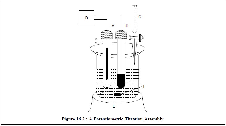
The various components shown in Figure 16.2, are as
follows :
A = Saturated Calomel Electrode (SCE),
B = Indicator Electrode,
C = Burette to discharge titrant in the reacting vessel,
D = pH Meter with a mV scale,
E = Magnetic stirrer with variable speed, and
F = Magnetic Guide.
1. ELECTRODES
The accurate, precise and effective potentiometric
measurements are evidently made with the aid of the following two types of electrodes namely :
(i) Reference Electrodes, such as :
(a) Standard
Hydrogen Electrode,
(b) Saturated
Calomel Electrode, and
(c)
Silver-silver Chloride Electrode.
(ii) Indicator Electrodes, such as :
(a) Metal
Indicator Electrode, and
(b) Membrane
Indicator Electrode.
These various kinds of electrodes will be discussed
briefly, along with a diagrammatic representation wherever possible, in the
sections that follow :
1.1. Reference Electrodes
In general, reference electrodes exhibit a potential
which is absolutely independent of the solution wherein it is used. Besides, it
must not display any significant change even when a small quantum of current is
passed through it.
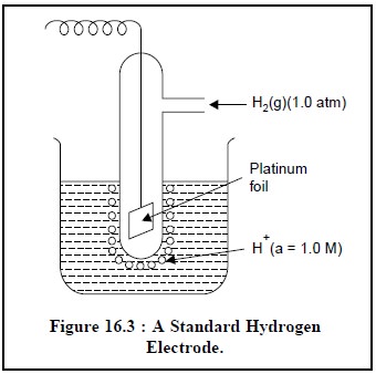
1.1.1. Standard Hydrogen Electrode (SHE)
The standard hydrogen electrode (SHE), as shown in Figure 16.3, is considered to be the
universally accepted reference electrode. The metal electrode comprises of a
small piece of platinum foil with a finely divided platinum,usually termed as
platinum black because of its dark look.The coated foil is immersed in an
acidic medium having a hydrogen ion activity of 0.1, and through which H2 gas
is bubbled at a partial pressure of 1.0 atm (unit activity). The Pt-black-foil
possesses a relatively large-surface-area thereby enabling it to absorb an
appreciable amount of H2+H (a = 1.0 M)
gas, ultimately bringing it into direct contact with the surrounding H+ ions at
the electrode surface. Consequently,the Pt-electrode attains a potential which
is finally estimated Figure 16.3 : A
Standard Hydrogen by the relative tendencies of H+ ions to undergo reduction
Electrode. and H2 (g) to undergo
oxidation simultaneously. It is an usual convention to assign the potential of
SHE a value exactly equal to zero at all temperatures.
1.1.2. Saturated Calomel Electrode
The schematic diagram of a commercial saturated calomel elec-trode (SCE) is depicted in Figure 16.4. It essentially consists of a plati-num wire immersed in a slurry made up of pure mercury, solid mercurous chloride Hg2Cl2 (commonly known as calomel), and aqueous saturated solution of KCl, packed in the inner-tube (c) having a small hole (B). The outer-tube contains a saturated solution of KCl (D) having a porous ce-ramic fiber (A) at its lower end. It serves as a salt-bridge which allows the entire set-up immersed directly into the solution to be measured. The po-rous ceramic fiber permits establishment of electrical contact between one side of the salt-bridge and the solution under the examination and serves as a barrier between the said two solutions. The small opening at the top end of the salt-bridge tube serves as a fill-hole (E) through which either KCl solution may be filled or replaced as and when required.
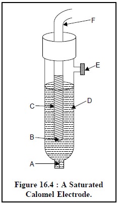
The differ-ent parts of the
saturated calomel electrode are as follows :
A = Porous ceramic fiber,
B = Small-hole,
C = Slurry of Hg, Hg2Cl2 and
saturated KCl, D = Saturated KCl solution,
E = Fill-hole, and
F = Electrical lead.
The half-cell of SCE may be expressed as :
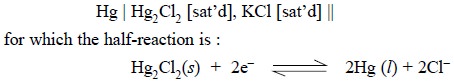
According to the Nernst equation, the potential of the
electrode is represented by :
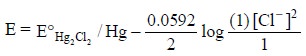
assuming the activities of Hg and Hg2Cl2
solid are both unity.
Advantages : The two major advantages of SCE are, namely :
(a)
Concentration of Cl– does not alter appreciably even if some of the
solvent gets evaporated, and
(b) Generates a
comparatively small junction potential (Ej)
at the two salt-bridge solution interfaces.
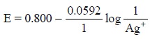
1.1.3. Silver-silver Chloride
Electrode
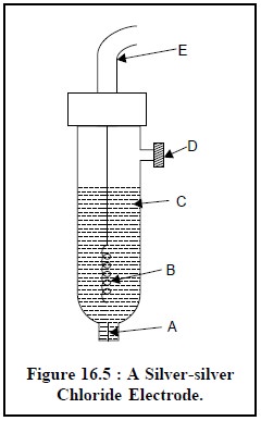
Figure 16.5 shows a silver-silver chloride electrode
which com-prises of a silver wire coated with silver chloride (B) and is duly
placed in a 1 M KCl solution saturated with AgCl (C).
The half-cell of silver-silver chloride electrode may be
represented as :

for which half-reaction would be :

According to the Nernst equation, the potential of the
electrode is expressed as :
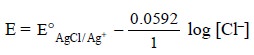
considering that the potential of the electrode is solely
dependent on the concentration of Cl–.
The various components of a silver-silver chloride
electrode are, namely :
A = Porous ceramic fiber,
B = Ag wire coated with AgCl,
C = 1 M KCl saturated with AgCl,
D = Fill-hole, and
E = Electrical lead.
1.2. Indicator Electrodes
An indicator electrode is invariably used exclusively in
conjunction with a reference electrode the response of which solely depends
upon the concentration of the analyte.
1.2.1. Metal Indicator Electrode
Metal indicator electrodes develop a potential which is
usually determined by the equilibrium posi-tion of a redox half-reaction at the
electrode surface. These are further classified into the following three types, namely :
(i) First order
electrodes,
(ii) Second
order electrodes, and
(iii) Inert
electrodes.
which shall be discussed briefly below.
1.2.1.1. First-order electrodes
They are essentially comprised of a metal placed in a
solution of its respective ions, for instance : a silver wire immersed into a
AgNO3 solution. Hence, the reversible half reaction may be
represented as:
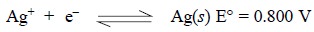
and the corresponding Nernst equation would be as follows
:
The metals that display reversible half reactions with
their respective ions and are found to be suitable for employing as first-order
electrodes are Ag, Hg, Cu, Cd, Zn, Bi, Pb and Sn. However, several other metals
like : Fe, Co, Cr and W are not useful due to the following reasons :
(i) Non-reproducible
potentials largely influenced by impurities,
(ii) Irregular
crystal structures in the solid-state, and
(iii) Formation
of oxide layers on their surfaces.
1.2.1.2. Second-order electrodes
Sometimes a metal electrode may be directly responsible to
the concentration of an anion which either gives rise to a complex or a
precipitate with the respective cations of the metal. Therefore, they are
termed as second-order electrodes as
they respond to an ion not directly involved in the electron transfer process.
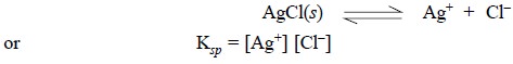
The silver-silver chloride
electrode, as already described, is a typical example of a second-order
electrode. In this particular instance, the coated Ag wire when dipped in a
solution, sufficient AgCl dissolves to saturate the layer of solution just in
contact with the respective electrode surface. Thus, the Ag+ ion
concentration in the said layer of solution may be determined by the status of
the solubility product (Ksp)
equilibrium :
Disadvantages : The four serious disadvantages are, namely :
(a) May be used
effectively over a certain range of anion concentration only so that the
solution must remain saturated with the substance coating the metal,
(b) In the case
of Ag-AgCl electrode, a very low Cl– ion concentration would
dissolve the AgCl-coating to a great extent,
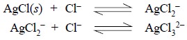
(c) Likewise, a
very high concentration of Cl– ion would result into the formation
of soluble complex ions as shown below :
(d) Ions like
Br–, I– SCN–, CN– and S2–
cause interference while using a Ag-AgCl electrode to esti-mate Cl–
ion concentrations because of the facts that these ions usually form salts with
Ag+ ion which are significantly less soluble than AgCl.
1.2.1.3. Inert electrodes
Inert electrodes comprise of chemically inert
conductors, for instance : Au, Pt and C which do not necessarily take part either directly or indirectly in the various
redox processes. However, the potential developed at an inert electrode solely
depends upon both the nature as well as the prevailing concentration of the
different redox-reagents present in the solution.
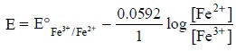
Example : A Pt-electrode placed in a
solution consisting of both Fe3+ and Fe2+ ions
develops a poten-tial which is duly represented by the Nernst equation for ions
as given below :
Advantages : The two main advantages of inert-electrodes are, namely :
(a) Exhibit no
chemical selectivity, and
(b) Respond to
any reversible redox-system.
1.2.2. Membrane Indicator Electrodes
(or Ion-Selective Electrodes)
The underlying principle of this type of electrode is
that the potential developed due to an unequal charge generated at the opposing
surfaces of a ‘special’ membrane. The resulting charge at each surface of the
membrane is exclusively controlled and monitored by the exact position of an
equilibrium involving analyte ions, which in turn, solely depends upon the
concentration of those ions present in the solution. Ion-selective electrodes
occupy a very important place in the analytical chemistry by virtue of the fact
that one may use the acquired skill, expertise and wisdom to design and
commercially prepare membranes that are practically selective towards a
specific ion besides producing potentials according to the Nernst-type
equation. These are classified further into the following four kinds, namely :
(i) Glass
membrane electrodes,
(ii) Polymer
(liquid) membrane electrodes,
(iii)
Crystalline membrane electrodes, and
(iv)
Gas-sensing electrodes,
which will be described below briefly :
1.2.2.1. Glass Membrane Electrodes
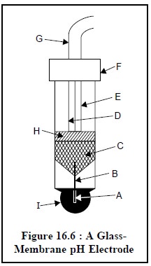
The diagram of a typical glass-membrane electrode is
depicted in Figure 16.6. The internal element essentially comprises of a
Ag-AgCl electrode (B) dipped in a pH 7 buffer saturated with AgCl (A). The
thin, ion-selective glass membrane (I) is carefully fused to the bottom of a
high resistance non-responsive glass tube (H) so that the entire membrane may
be immersed while taking measurements.
The half-cell of glass-membrane electrode may be
expressed as :
Ag (s) | AgCl [saturated], Cl– (inside), H+
(inside) | glass membrane | H+ (outside)
According to the Nernst equation, the potential of the
electrode is represented by :
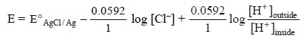 .......................(i)
Now, separating the ratio of H+ ion
concentrations into two log terms we may have :

As the activities (i.e.,
concentrations) of H+ and Cl– in the internal electrolyte
solution are constant, the first three components on the right hand side of Eq.
(ii) may be confined into a single
constant, K, and the equation could be rewritten as :
E = K + 0.0592 log [H+]outside
The various components
of Figure 16.6 are as follows :
A = pH 7.0 buffer
solution saturated with AgCl,
B = Ag-AgCl internal
reference electrode,
C = Mercury connection,
D = Connecting wire,
E = Shield,
F = Cap,
G = Shielded and
insulated connecting wire,
H = High resistance
non-responsive glass, and
I = H+–selective glass
membrane.
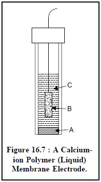
1.2.2.2. Polymer (Liquid) Membrane Electrode
Figure 16.7. illustrates a calcium-ion polymer (liquid)
membrane electrode. It has a close similarity to the glass pH electrode, and it
essentially comprises of an internal Ag-AgCl electrode (B) and an internal
reference solution having a fixed composition e.g., aqueous CaCl2 saturated with AgCl (C). The liquid
calcium di (n-decyl) phosphate, [{CH3(CH2)8CH2O}2PO2]2
Ca serves as the membrane, positioned at the lower end of the electrode, and
strategically immobilized by a thin disk of PVC (polyvinyl chloride) (A) which
is not penetrable with water.
Thus, the calcium di (n-decyl)
phosphate forms an equilibrium with its ions at every membrane surface :
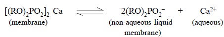
where, R = CH3(CH2)8 –CH2–
i.e., n-decyl hydrocarbon chain.
Interestingly, the didecylphosphate anion represents a
fixed component of the non-aqueous liquid membrane. As the concentration of Ca+
ions present in the solutions on either side of the membrane varies ; hence,
the concentration of didecylphosphate anion at every membrane surface would
also vary accordinly, thereby causing a potential that may be expressed by the
following equation :
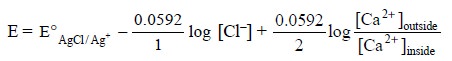 ..........................(i)
Again, separating the ratio of Ca2+ ion
concentration into two log terms we have :

Since the activities of Ca2+ and Cl–
in the internal electrolyte solution are more or less constant, the first three
terms on the right hand side of Eq. (ii)
may be combined to a single constant, K, and the same equation may be rewritten
as follows :
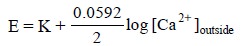 .....................(iii)
The different essential components of Figure 16.7 are as
stated below :
A = Calcium di (n-decyl)-phosphate
immobilizes in PVC,
B = Silver-silver chloride electrode, and
C = Aqueous CaCl2 saturated with AgCl.
1.2.2.3. Crystalline Membrane Electrodes
The crystalline membrane electrodes have a very close
similarity to those of glass-membrane electrodes except that glass has been
replaced with crystalline membrane. In fact, these electrodes offer a means to
devise responsive to anions by making use of a membrane containing specific
anionic sites.
Example : Fluoride-ion
Electrode : In
this particular instance the mem-brane essentially comprises of a single
crystal of lanthanum fluoride (LaF3), usually doped with a slight
trace of europium (II), Eu2+, so as to initiate the crystal defects
required for establishing its electrical conductivity. Therefore, the potential
developed at each surface of the membrane is finally determined by the exact
status of the equilibrium :
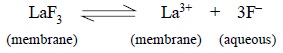
and is represented by the following equation :
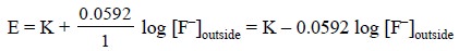
Salient features of Fluoride-Ion Electrode are, namely :
(a) At low pH,
F– ion gets readily converted to the weak acid HF (pKa = 3.17)
thereby rendering the electrode insensitive,
(b) It is
almost 103 times more specific and selective for F– ion
as compared to other common anions, of course with the exception of OH–
ion, and
(c) This electrode can tolerate conveniently the
maximum concentration of OH– ion to the extent of 1/10th as compared to the F–
ion concentration.
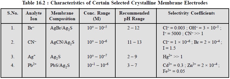
Table 16.2 records the characteristics of certain
selected crystalline-membrane electrodes.
1.2.2.4. Gas-Sensing Electrode
The schematic diagram of
a gas-sensing electrode is illustrated in Figure 16.8, that comprises of
essentially a reference electrode (E), a specific-ion electrode (B), and internal electrolyte solution (F) contained
in a cylindrical plastic tube (G). One end of the plastic tubing is provided
with a thin, replaceable, gas-permeable membrane that separates the internal
electrolyte solution from the external solution containing gaseous analyte.
However, the exact composition and specifications of this gas-permeable membrane
is usually described by
its respective manufacturers. It is normally made up of a thin
microporous film fabricated from a hydrophobic plastic material.
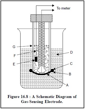
The various components
of Figure 16.8 are as follows :
A = Gas permeable
membrane,
B = Specific ion
electrode (a glass electrode),
C = ‘O’-Ring to hold the
membrane,
D = External solution
containing dissolved gaseous analyte,
E = Reference electrode
(a Ag/AgCl electrode),
F = Internal electrolyte
solution, and
G = Plastic tube.
In general, it must fulfil the following requirements,
namely :
(a) It should
act as a 100% barrier for both water and electrolytes i.e., they must not pass through this membrane,
(b) Pores of
the film contain exclusively air or other gases to which it is exposed, and
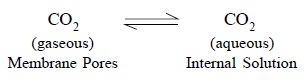
(c) A solution
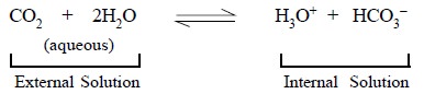
containing a particular gaseous-analyte, for instance CO2, when
comes in contact with the membrane the former migrates swiftly into the pores
of the latter, as expressed by the follow-ing reaction :
 .......................(a)
As the number of pores in the gas-permeable membrane are
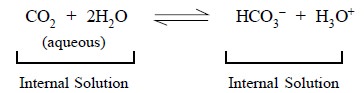
plenty, therefore, an equilibrium is established. Evidently, the carbon-dioxide
present in the pores is in direct contact with the internal-electrolyte
solution (F), thereby giving rise to a second equilibrium reaction that may be
represented as follows :
 ............................(b)
As a result of the above two reactions, Eq. (a) and Eq. (b), the external solution containing dissolved gaseous analyte (D)
immediately attains an equilibrium with the film of internal electrolyte
solution (F) present very close to the gas-permeable membrane (A). Thus,
another equilibrium gets established that affords the pH of the
internal-surface film to alter according to the following expression :
 .........................(c)
The above change in pH is instantly detected by means of
a Ag/AgCl reference electrode pair (E) dipped in the film of internal solution
as shown in Figure 16.8.
Therefore, the net overall reaction caused by the entire
aforesaid process may be achieved by simply summing up the three chemical reactions (a),
(b), and (c) to give :
 .............................(d)
The equilibrium constant, K, for Eq. (d) may be represented by :
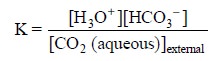 ..............................(e)
Assuming that the concentration of HCO3–present
in the internal-electrolyte solution (F) is made comparatively high such that
its concentrations do not undergo any appreciable change due to the migrating
CO2, we may have :
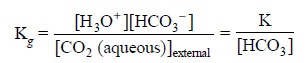 .............................(f)
Thus, Eq. (f)
may be rewritten as follows :
 ...........................(g)
where, a1 = Internal hydrogen ion activity
It is given that :
Ecell = L + 0.0592 log a1 ...(h)
Consequently, the potential of the electrode system
present in the internal-electrolyte solution (F) is solely dependent on a1 according to Eq. (h). Hence, substituting Eq. (g) into Eq. (h), we may have :
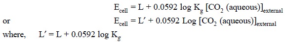
In short, therefore, the potential of the cell comprising
of the Ag/AgCI reference electrode (E) i.e.,
the internal reference and the specific ion electrode (B) i.e., the indicator electrode is normally determined by the CO2
concentration of the external solution containing dissolved gaseous analyte.
Notes : (i) None of the electrodes
(reference & indicator) ever gets in contact directly with the analyte
solution, and
(ii) The only substances which may cause
interference with the measurement of potential are dissolved gases which may have a free-access through the membrane,
and in turn may affect the pH of the internal solution accordingly.
Selectivity of Gas-sensing
Electrode : The
selectivity of the gas-sensing electrode may be enhanced by making use of such an internal electrode which is particularly
sensitive enough to certain species other than the H+ ion.
Example : Nitrate-sensing electrode is
employed to cater for a cell which will be sensitive exclusively to
nitrogen dioxide (NO2). The equilibrium of such a reaction may be
represented as follows :
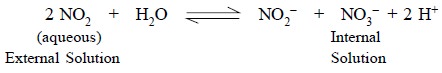
The nitrate-sensing electrode allows the determination of
NO2 in the presence of certain specific gases only, for instance, NH3,
SO2 and CO2, that will also affect the change in pH of
the internal electrolyte solution significantly.
2. AUTOMATIC TITRATOR (PRESET END-POINT TITRATOR)
The schematic diagram of an automatic titrator* is shown
in Figure 16.9.
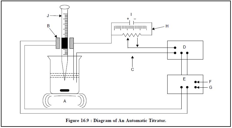
The various components of Figure 16.9 are, namely :
A = Magnetic stirrer with a Regulator,
B = Solenoid valve, and
C = Error Signal,
D = Amplifier,
E = Electronic Switch,
F and G = AC-Source,
H = End-point Potential,
I = Calibrated Potentiometer, and
J = Accurately calibrated Burette.
In this case a preset equivalence point potentiometer is
applied at the two electrodes with the aid of a calibrated potentiometer (I).
It will give rise to an “error” signal (C) provided a difference is caused
between this potential and that of the electrodes. The feeble signal thus
generated is duly amplified (D) and closes an electronic switch (E) which
allows the electricity to flow through the solenoid operated value (B) of the
burette (J). As the titration proceeds, the error signal (C) starts approaching
a zero value, subsequently the current to the solenoid valve (B) is instantly
switched off, and finally the flow of titrant from the burette (J) comes to a
halt. The solution of the sample is constantly and uniformly stirred with the
help of a magnetic stirrer (A).
Related Topics