Chapter: Electronic Devices and Circuits : Amplifiers
Low frequency analysis of amplifier to obtain lower cut-off frequency
Low frequency analysis of amplifier to obtain lower cut-off frequency:
Ø Decibel Unit:
The decibel is a logarithmic measurement of the ratio of one power to another or one voltage to another. Voltage gain of the amplifier is represented in decibels (dBs). It is given by,
Voltage gain in dB = 20 log Av
Power gain in decibels is given by,
Power gain in dB = 10 log Ap
Where Av is greater than one, gain is positive and when Av is less than one, gain is negative. The positive and negative gain indicates that the amplification and attenuation respectively. Usually the maximum gain is called mid frequency range gain is assigned a 0 db value. Any value of gain below mid frequency range can be referred as 0 db and expressed as a negative db value.
Example:
Assume that mid frequency gain of a certain amplifier is 100. Then,
Voltage gain = 20 log 100 = 40 db
At f1 and f2 Av = 100/√2 = 70.7
Voltage gain at f1 = Voltage gain at f2 = 20 log 70.7 = 37 db
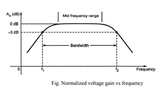
From above figure, it shows that the voltage gain at f1 and f2 is less than 3db of the maximum voltage gain. Due to this the frequencies f1 and f2 are also called as 3 db frequencies. At f1 & f2 power gain drops by 3 db. For all frequencies within the bandwidth, amplifier power gain is at least half of the maximum power gain. This bandwidth is also referred to as 3 db bandwidth.
Ø Significance of octaves and decades:
The octaves and decades are the measures of change in frequency. A ten times change in frequency is called a decade. Otherwise, an octave corresponds to a doubling or halving of the frequency.
Example:
An increase in frequency from 100 Hz to 200 Hz is an octave.
A decrease in frequency from 100 kHz to 50 kHz is also an octave.
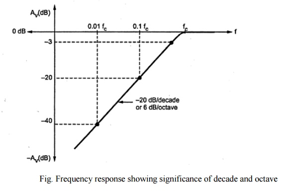
At lower and higher frequencies the decrease in the gain of amplifiers is often indicated in terms of db/decades or db/octaves. If the attenuation in gain is 20 db for each decade, then it is indicated by line having slope of 20 db/decade. A rate of -20 db/decade is approximately equivalent to - 6db/octave. A rate of -40 db/decade is approximately equivalent to -12db/octave.
Ø Midband gain:
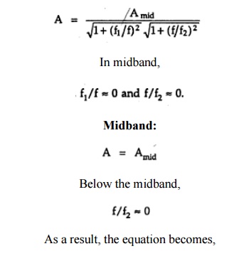
It is defined as the band of frequencies between 10 f1 and 0.1 f2. It is denoted as midband gain or Amid.
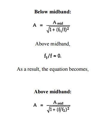
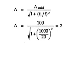
The voltage gain of the amplifier outside the midband is approximately given as,
· Problem:
For an amplifier, midband gain = 100 and lower cutoff frequency is 1 kHz. Find the gain of an amplifier at frequency 20 Hz.
Solution:
Below midband:
Effect of various capacitors on frequency response:
ü Effect of coupling capacitors:
The reactance of the capacitor is Xc = 1/2∏fc
At medium and high frequencies, the factor f makes Xc very small, so that all coupling capacitors behave as short circuits. At low frequencies, Xcincreases. This increase in Xc drops the signal voltage across the capacitor and reduces the circuit gain. As signal frequencies decrease, capacitor reactance increase and gain continues to fall, reducing the output voltage.
ü Effect of Bypass capacitors:
At lower frequencies, bypass capacitor CE is not a short. So emitter is not at ac ground. Xc in parallel with RE creates an impedance. The signal voltage drops across this impedance reducing the circuit gain.
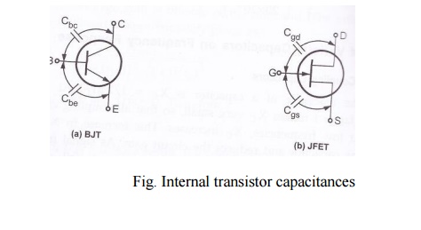
ü Effect of internal transistor capacitances:
At high frequencies, coupling and bypass capacitors act as short circuit and do not affect the amplifier frequency response. At high frequencies, internal capacitances, commonly known as junction capacitances. The following figure shows the junction capacitances for both BJT and FET. Incase of BJT, Cbe is the base emitter junction capacitance and Cbc is the base collector junction capacitance. Incase of FET, Cgs is the internal capacitance between gate and source and Cgd is the internal capacitance between gate and drain.
Related Topics