Chapter: Transmission Lines and Waveguides : Waveguides and Cavity Resonators
General Wave behaviors along uniform, Guiding structures
General Wave behaviors along uniform, Guiding structures
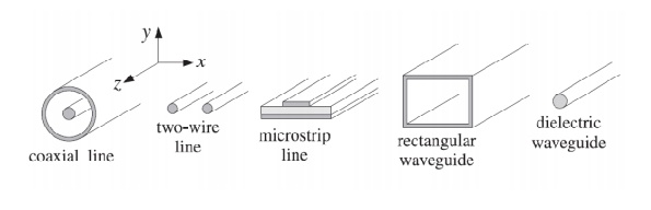
Waveguides are used to transfer electromagnetic power efficiently from one point in space to another. Some common guiding structures are shown in the figure below. These include the typical coaxial cable, the two-wire and micro strip transmission lines, hollow conducting waveguides, and optical fibers.
• In practice, the choice of structure is dictated by: (a) the desired operating frequency band,
(b) the amount of power to be transferred, and (c) the amount of transmission losses that can be tolerated.
• Coaxial cables are widely used to connect RF components. Their operation is practical for frequencies below 3 GHz. Above that the losses are too excessive. For example ,the attenuation might be 3 dB per 100 m at 100 MHz, but 10 dB/100 m at 1GHz, and50 dB/100 m at 10 GHz.
• Their power rating is typically of the order of one kilowatt at100 MHz, but only 200 W at 2 GHz, being limited primarily because of the heating of the coaxial conductors and of the dielectric between the conductors (dielectric voltage breakdown is usually a secondary factor.) However, special short-length coaxial cables do exist that operate in the 40 GHz range.
• Another issue is the single-mode operation of the line. At higher frequencies, in order to prevent higher modes from being launched, the diameters of the coaxial conductors must be reduced, diminishing the amount of power that can be transmitted. Two-wire lines are not used at microwave frequencies because they are not shielded and can radiate. One typical use is for connecting indoor antennas to TV sets. Micro strip lines are used widely in microwave integrated circuits.
• Rectangular Waveguides Next, we discuss in detail the case of a rectangular hollow waveguide with conducting walls, as shown in Fig. Without loss of generality, we may assume that the lengths a, b of the inner sides satisfy b ≤ a. The guide is typically filled with air, but any other dielectric material ε, µ may be assumed.
Wave propagation in free space.
Free space is a region where these are nothing - the vacuum of outer space is a fair approximation for most purposes. There are no obstacles to get in the way, no gases to absorb energy, nothing to scatter the radio waves. Unless you are into space communications, free space is not something you are likely to encounter, but it is important to understand what happens to a radio wave when there is nothing to disturb it.
In free space, a radio wave launched from a point in any given direction will propagate outwards from that point at the speed of light. The energy, carried by photons, will travel in a straight line, as there is nothing to prevent them doing so. For all practical purposes, a radio wave when launched carries on in a straight line forever traveling at the speed of light.
Free space loss is not really a loss at all. It relates to the intensity of the wave at a distance from the source measured by some standard collector, like an antenna or a telescope. As the wave spreads out, the intensity becomes lower.
Consider a radio wave source that radiates in all directions with equal intensity from a single point (like a light bulb).
All the points at a given radius r from a single point form the surface of a sphere and the total energy is uniformly spread out over the area of this sphere (remember our source is radiating equally in all directions). So the amount of energy that can be collected over the section of the total area represented by our collector is proportional to the ratio of the "capture area" of our collector to the total area.
The area of this sphere is proportional to the radius: Area =
The power per unit area is simply the total power divided by the total area. If the power is measured in watts this is: Watts / m2 = Total watts / total area in m2
This power is usually referred to as the power flux density: Power flux density = P /
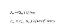
The amount of power collected by an ideal antenna is simply the power flux density multiplied by the effective capture area of the antenna Ae.

The effective capture area of an antenna is related to the gain of the antenna. If the Gain of the receiving antenna is Grx the following holds:
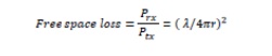
Normalising this to a receiver antenna of unity gain so Grx =1, the ratio of the received power to the transmitted power which is the proportion we "lose" on the path is called the free space loss represented by:
The electromagnetic waves that are guided along or over conducting or dielectric surface are called guided waves.
Examples: Parallel wire, transmission lines
Cut off frequency is the wavelength below which there is wave propagation and above which there is no wave propagation.
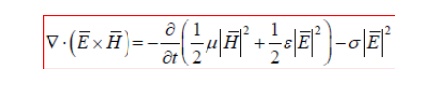
Poynting’s theorem:
Poynting’s theorem is a hugely important mathematical statement in electromagnetic that concerns the flow of power through space. Poynting's theorem is a statement of conservation of energy for the electromagnetic field, in the form of a partial differential equation. Poynting's theorem is analogous to the work-energy theorem in classical mechanics, and mathematically similar to the continuity equation, because it relates the energy stored in the electromagnetic field to the work done on a charge distribution (i.e. an electrically charged object), through energy flux.
The wave polarization is defined by the time behavior of the electric field of a TE M wave at a given point in space. In other words, the state of polarization of a wave is describe d by the geometricals hape which the tip of the electric field vector draws as a function of time at a given point in space. Polarization is a fundamental characteristic of a wave, and every wave has a definite state of polarization.
Related Topics