Chapter: Mechanical : Fluid Mechanics And Machinery : Flow Through Circular Conduits
Flow Through Circular Conduits
FLOW THROUGH CIRCULAR CONDUITS
PRE REQUEST DISCUSSION
This page has an in dept dealing of laminar flow through pipes, boundary layer concept, hydraulic and energy gradient, friction factor, minor losses, and flow through pipes in series and parallel.
Boundary layer is the region near a solid where the fluid motion is affected by the solid boundary. In the bulk of the fluid the flow is usually governed by the theory of ideal fluids. By contrast, viscosity is important in the boundary layer. The division of the problem of flow past an solid object into these two parts, as suggested by Prandtl in 1904 has proved to be of fundamental importance in fluid mechanics.
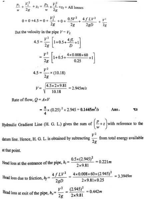
This concept of hydraulic gradient line and total energy line is very useful in the study of flow This concept of hydraulic gradient line and total energy line is very useful in the study of flow of fluids through pipes. f fluids through pipes.
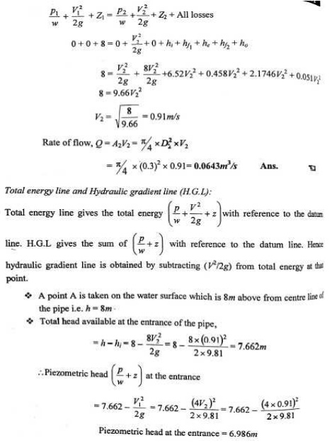
HYDRAULIC GRADIENT AND TOTAL ENERGY LINE
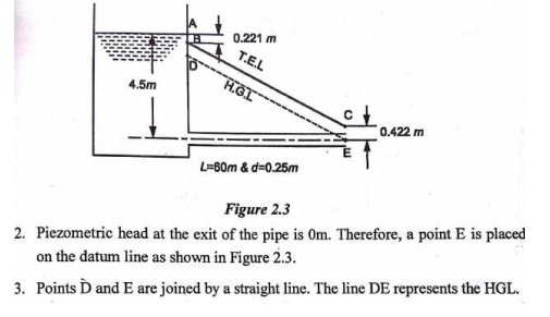
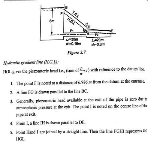
1.Hydraulic Gradient Line
It is defined as the line which gives the sum of pressure head (p/w) and datum head (z) of a flowing fluid in a pipe with respect to some reference line or it is the line which is obtained by joining the top of all vertical ordinates, showing the pressure head (p/w) of a flowing fluid in a pipe from the centre of the pipe. It is briefly written as H.G.L (Hydraulic Gradient Line).
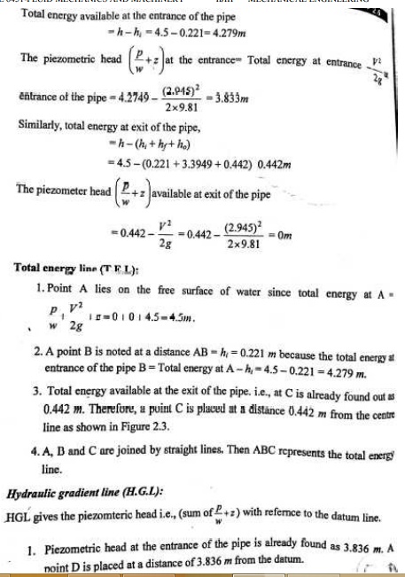
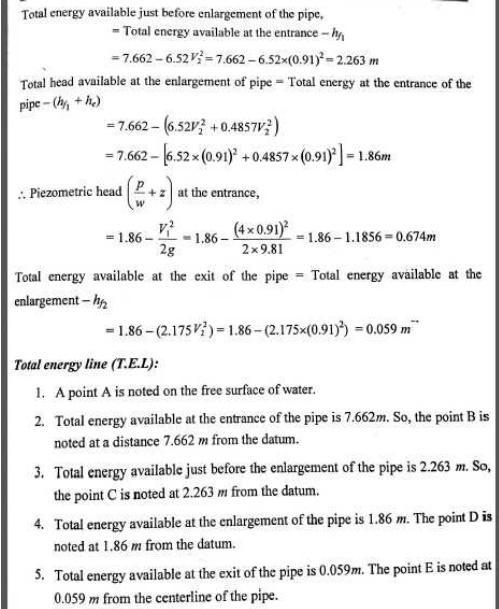
2.Total Energy Line
It is defined as the line which gives the sum of pressure head, datum head and kinetic head of a flowing fluid in a pipe with respect to some reference line. It is also defined as the line which is obtained by joining the tops of all vertical ordinates showing the sum of pressure head and kinetic head from the centre of the pipe. It is briefly written as T.E.L (Total Energy Line).
BOUNDARY LAYER
Concepts
The variation of velocity takes place in a narrow region in the vicinity of solid boundary. The fluid layer in the vicinity of the solid boundary where the effects of fluid friction i.e., variation of velocity are predominant is known as the boundary layer.
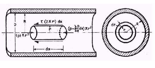
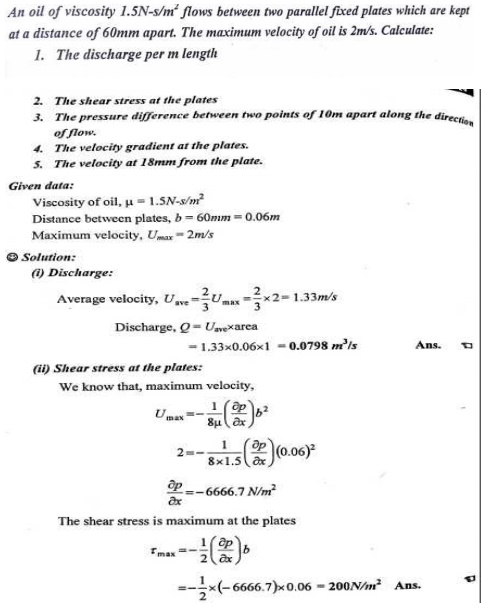
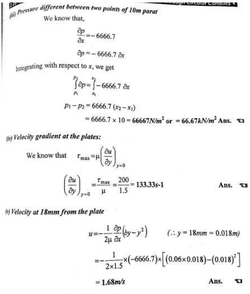
1 FLOW OF VISCOUS FLUID THROUGH CIRCULAR PIPE
For the flow of viscous fluid through circular pipe, the velocity distribution across a section, the ratio of maximum velocity to average velocity, the shear stress distribution and
drop of pressure fora given length is to be determined. The flow through circular pipe will be viscous or laminar, if the Reynold’s number is less than 2000.
.2 DEVELOPMENT OF LAMINAR AND TURBULENT FLOWS IN CIRCULAR PIPES
1.Laminar Boundary Layer
At the initial stage i.e, near the surface of the leading edge of the plate, the thickness of boundary layer is the small and the flow in the boundary layer is laminar though the main stream flows turbulent. So, the layer of the fluid is said to be laminar boundary layer.
2.Turbulent Boundary Layer
The thickness boundary layer increases with distance from the leading edge in the down-stream direction. Due to increases in thickness of boundary layer, the laminar boundary layer becomes unstable and the motion of the fluid is disturbed. It leads to a transition from laminar to turbulent boundary layer.
3 BOUNDARY LAYER GROWTH OVER A FLAT PLATE
Consider a continuous flow of fluid along the surface of a thin flat plate with its sharp leading edge set parallel to the flow direction as shown in figure 2.7.The fluid approaches the plate with uniform velocity U known as free stream velocity at the leading edge. As soon as the fluid comes in contact the leading edge of the plate,its velocity is reduced to zero as the fluid particles adhere to the plate boundary thereby satisfying no-slip condition.
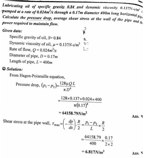
FLOW THROUGH CIRCULAR PIPES-HAGEN POISEUILLE’S EQUATION
Due to viscosity of the flowing fluid in a laminar flow,some losses of head take place.The equation which gives us the value of loss of head due to viscosity in a laminar flow is known as Hagen-Poiseuille’s law.
p1-p2=32μUL/D²
=128μQL/πD4
This equation is called as Hargen-Poiseuille equation for laminar flow in the circular pipes.
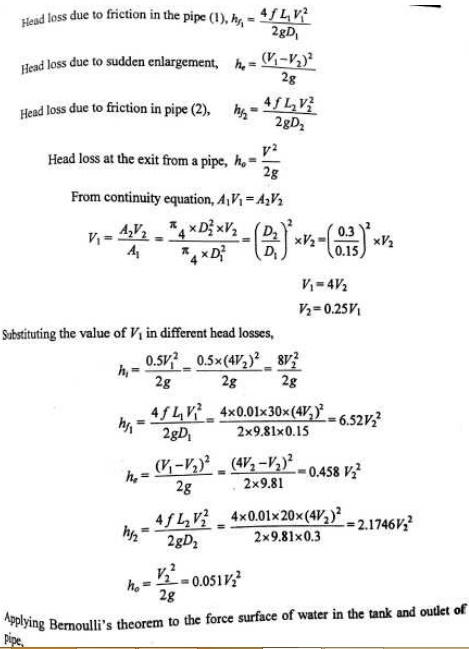
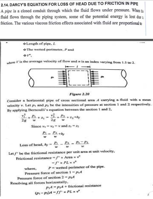
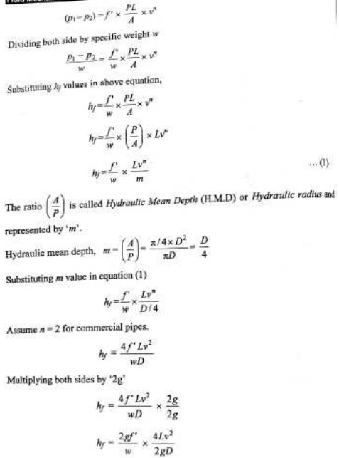
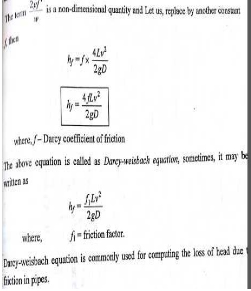
DARCY’S EQUATION FOR LOSS OF HEAD DUE TO FRICTION IN PIPE
A pipe is a closed conduit through which the fluid flows under pressure.When the fluid flows through the piping system,some of the potential energy is lost due to friction.
hƒ=4ƒLv²/2gD
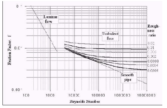
MOODY’S DIAGRAM
Moody’s diagram is plotted between various values of friction factor(ƒ),Reynolds
number(Re) and relative roughness(R/K) as shown in figure 2.6.For any turbulent flowproblem,the values of friction factor(ƒ) can therefore be determined from Moody’s diagram,if the numerical values of R/K for the pipe and Rе of flow are known.
The Moody’s diagram has plotted from the equation
1/√ ƒ-2.0 log10(R/K)=1.74-2.0 log10[1+18.7/(R/K/Re/ ƒ)]
Where,R/K=relative roughness
ƒ=friction factor and Re=Reynolds number.
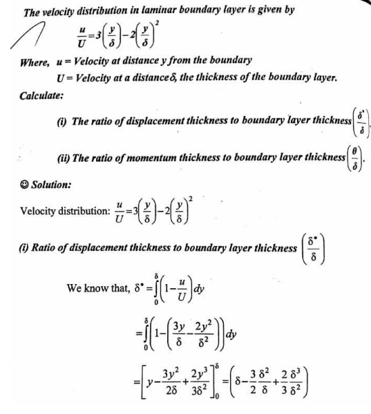
CLASSIFICATION OF BOUNDARY LAYER THICKNESS
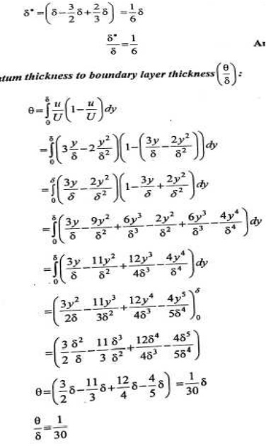
1. Displacements thickness(δ*)
2. Momentum thickness(θ)
3. Energy thickness(δe)
BOUNDARY LAYER SEPARATION
The boundary layer leaves the surface and gets separated from it. This phenomenon is known as boundary layer separation.
LOSSESS IN PIPES
When a fluid flowing through a pipe, certain resistance is offered to the flowing fluid, it results in causing a loss of energy.
The loss is classified as:
1. Major losses
2. Minor losses
Major Losses in Pipe Flow
The major loss of energy is caused by friction in pipe. It may be computed by Darcy-weisbach equation.
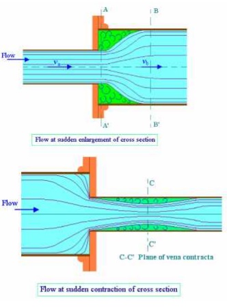
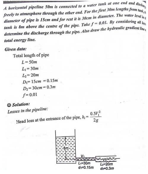
Minor Losses in Pipe Flow
The loss of energy caused on account of the change in velocity of flowing fluid is called minor loss of energy.
FLOW THOUGH PIPES IN SERIES AND PARALLEL
Pipes in Series
The pipes of different diamers and lengths which are connected with one another to form a single pipeline.
Pipes in Parallel
When a main pipeline divides into two or more parallel pipes which again join together to form a single pipe and continuous as a main line
GLOSSARY
HGL –Hydraulic gradient line
TEL – Total energy line.
Applications
1. To find out friction factor in the flow through pipe.
2. To find out the losses in losses in the pipes.
Related Topics