Chapter: Solid State Drives : Induction Motor Drives
Field Weakening Mode
Field Weakening Mode
In the field of closed loop controlled voltage source inverter- fed induction motors the rotor flux oriented control scheme can be regarded as the state of the art for various applications. In some applications as spindles, traction and electric vehicle drives the availability of constant power operation is very important. A field-oriented induction motor drive is a suitable candidate for such applications because the flux of the induction machine can be easily weakened. In this case the drive operates close to the voltage limit and the reference flux has to be carefully selected to achieve the maximum torque Control of an induction motor with weakened flux has been investigated by many authors and three methods for establishing the flux were suggested
1) The flux reference can be set according to a fixed flux- speed characteristic
2) it can be calculated from simplified motor equations, which can be improved through consideration of additional variables
3) it can be provided by a voltage controller, which sets the flux in such a way that the voltage required by the motor matches the voltage capability of the inverter
The third strategy seems to be optimal because it is not sensitive to parameter variations in a middle speed region. At high speed the current has to be reduced for matching the maxi - mum torque and for avoiding a pull-out. In this is done with a fixed current-speed characteristic which is sensitive to parameter and DC link voltage variations. A remedy is possible if a parameter insensitive feature of the induction machine is used for the current reduction. Such a criterion is presented and an extension of the voltage control is presented in this paper which allows an operation with maximum torque in the whole field weakening region
THE STEADY STATE TORQUE CAPABILITY
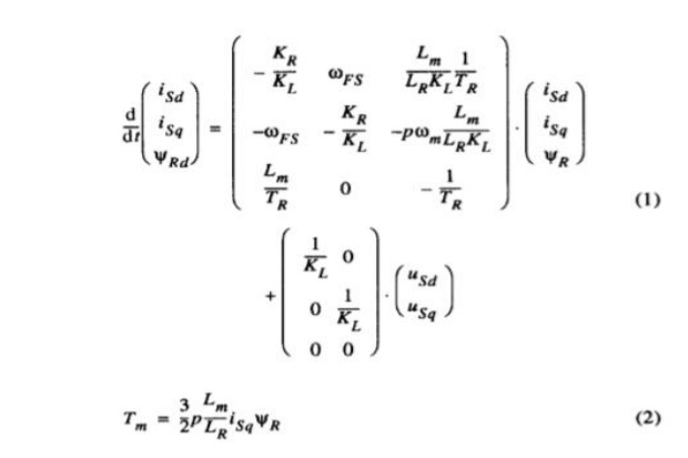
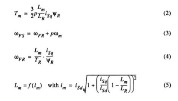
The investigation starts with the dynamic model of the induction motor in the rotor flux oriented frame
The voltage limitation curves depend on rotor speed. For every rotor speed any operation point below the voltage and the current limitation curve is possible and permissible. Obviously three speed regions have to be distinguished Basic speed region: At low speeds the peak of the cur- rent limit curve is situated below the voltage limit curve (e. g. curve b) with lo00 rpm). The maximum torque is determined by the peak of the current limitation curve and the corresponding rotor flux Root has to chosen.
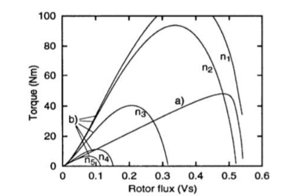
Lower flux weakening region: At medium speeds the maximum torque is indicated by the crossing of both limitation curves (e. g. curve a) and b) with 2500 rpm). The induction machine has to run with minimum current and maximum voltage.
Upper flux weakening region: At high speeds the maxi- mum torque is fixed by the maxima of the voltage limitation curves only. The machine has to run only with maximum voltage but the current has to be reduced.
In the lower flux weakening region the optimum operating point can be adjusted independently of the electrical parameters if the control scheme makes sure that the induction machine runs with maximum current and voltage.
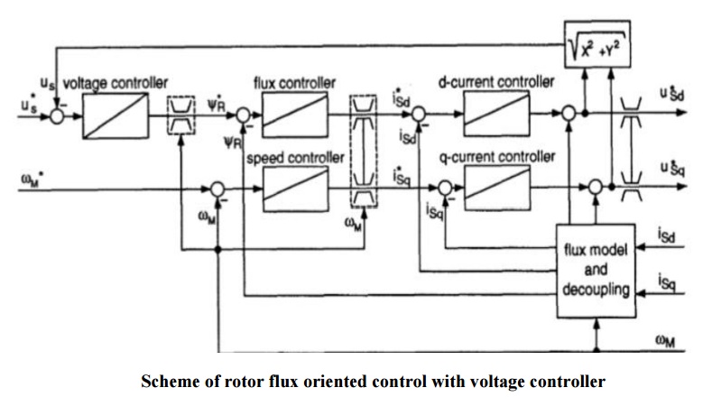
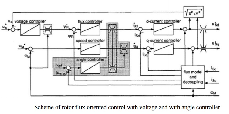
Fig. 2 shows a scheme that keeps these two conditions ([3], [lo]). The voltage controller increases the flux of the induction motor until the voltage matches the reference value us that is nearly the same as the voltage maximum
At the basic speed region the induction motor must not run at the voltage limit. The missing condition to adjust the operating point is replaced by the limitation of the reference flux. This is chosen as that determined the peak of the current limitation curve.
At the upper flux weakening region the limitation of the reference q-current is carried out with a speed depending function is max (am) that is calculated offline in such a way that de reduced current limitation curve crosses the voltage limitation curves at their maxima in Fig
CURRENT REDUCTION IN THE UPPER FLUX WEAKENING REGION
The function Iq max (n) depends on the electrical parameters as well as the DC link voltage. If the uncertainties of the electrical parameters and the variations of u d are taken into account the optimum operating point can be missed. This problem can be solved, if there is a second condition that describes the optimum operating point in the upper flux weakening region independently of the critical parameters. A condition that describes the optimum operating point independent of the electrical parameters can only depend on the measured values of current, voltage and speed. Since the torque has to be optimized for a given speed the measured value of the speed delivers no information.
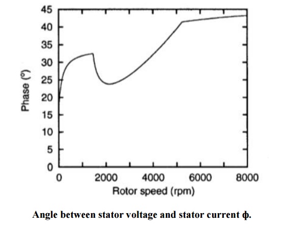
The amplitudes of the remaining voltage and current values are analyzed by means of Fig. 1 but additional information can be extracted from the angle between these quantities. The angle can be gathered from Fig. 3 that shows the locus of apparent power depends on speed if the motor runs with maximum torque. The three speed regions can be separated in this diagram as well as in Fig Basic speed region (0 rpm ... 1457 rpm): The stator voltage increases with speed and also the active and reactive power. Lower flux weakening region (1457 rpm...5240 rpm): The motor runs with maximum voltage and current. This results in = const. Upper flux weakening region (5240 rpm.. .8000 rpm): The current is reduced and also the apparent power.
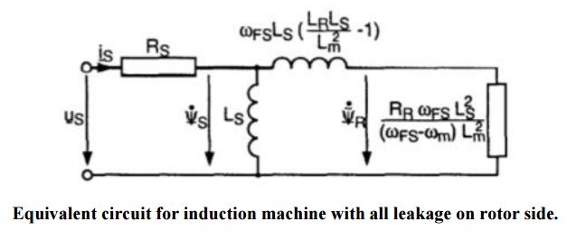
Remarkable is the phenomenon that the angle Ѱ between us and Is is nearly 450 and constant at the upper flux weakening region. This is also true for machines with other parameters. The reason can be deduced from the equivalent circuit of the induction motor at steady state (Fig. ). In the upper flux weakening region with the corresponding high excitation frequencies the magnetizing current as well as the influence of the stator resistance can be neglected. The maximum active power for a given voltage and excitation frequency is achieved if leakage reactance and rotor resistance are equal and
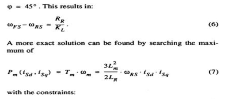
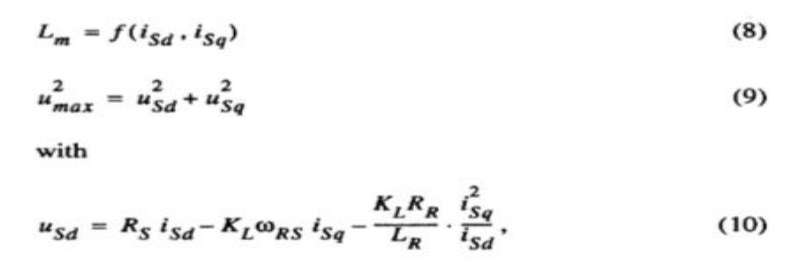
With these equations the torque is maximized for a given rotor speed and not for a given excitation frequency as with equ. (6) And in some papers.
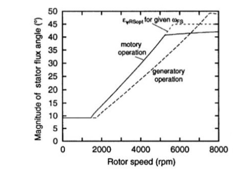
Optimal angle of stator flux in the rotor flux frame
The different operation areas are characterized by different behavior
In the basic speed region EѰRSPOT is small and constant.
In the lower flux weakening region the angle is characterized by a monotonous increase with a large gradient.
In the upper flux weakening region EѰRSPOT increases monotonously as well but the gradient is very small. As proposed EѰRSPOT is just a few degrees below 450 and nearly the same as Ѱ in this speed range. These quantity can be utilized advantageously as a criterion for the optimum operating point.
During generatory operation the upper flux weakening region is very small; the angle is negative and its magnitude runs above 450
The result of the simplified optimization for the upper flux weakening region is also presented in Fig. This curve runs just below 45 0 (exactly 450 if RS = 0 ) and the corresponding operation points are identical to the well-known pullout torque of the induction machine which characterizes the maxi- mum torque if the machine is excited with a fixed voltage and frequency. But these operation points represents not the maxi- mum torque for excitation with variable frequency and constant voltage. A larger torque can be attained for a given rotor speed if the machine runs with a smaller slip and excitation frequency and a therefore larger flux amplitude.
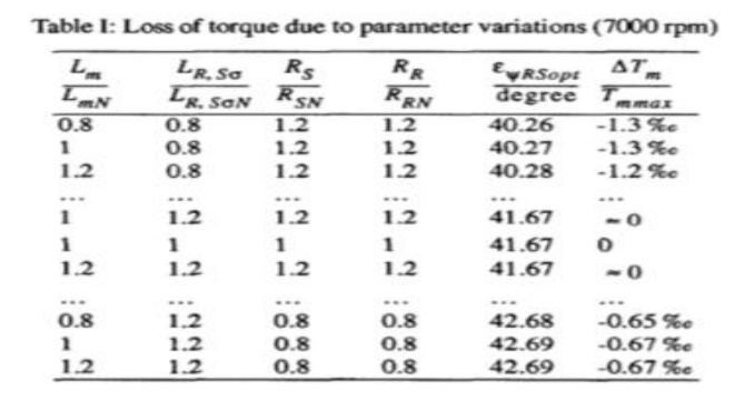
The robustness of the stator flux angle EѰRSPOT is demonstrated with Table I. In this table the results of EѰRSPOT! for a fixed rotor speed are listed which can be obtained if variations of the electrical parameters (factor: 0.8, 1.0, 1.2) are allowed and all 81 combinations are examined. The rows are sorted to increasing EѰRSPOT.In spite of the large variations the maxi- mum and the minimum of EѰRSPOT differ only little from the correct value 41.670. For these calculations the saturation of the mutual inductance was neglected and in this case EѰRSPOT is independent of the stator voltage. The last column shows the loss of torque if the induction machine runs with EѰRSPOT calculated from the detuned parameters. An extreme robustness to parameter uncertainties can be realized.
The current reduction by means of the stator flux angle can be easily implemented in the control scheme. One solution with little expense is shown in Fig. 7. The flux model delivers additionally an estimated value of the difference to EѰRSPOT is applied to an integrator which operates as an angle controller. Its regulating quantity is the limit of the reference q-current. If (E I > EѰRSPOT) the q-current will be reduced until the regulated quantity meets its reference value EѰRSPOT.
The quality of the operation point adjustment depends apparently on the quality of the flux estimation but at the relevant large rotor speeds a robust flux estimation is not difficult and uncritical. Furthermore, EѰRS coupled closely to the measurable angle Ѱ in this speed range.
Related Topics