Chapter: Civil : Mechanics Of Solids : Deflection Of Beams
Deflection Of Beams: Euler equation
Euler equation
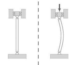
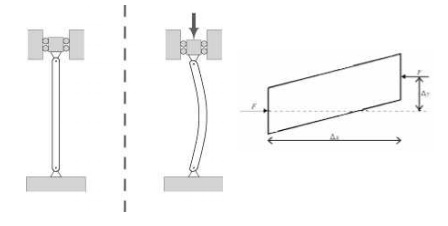
A column under a concentric axial load
exhibiting the characteristic deformation of buckling
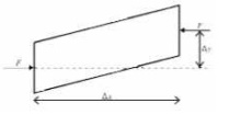
The eccentricity of the axial
forrce results in a bending moment acting on the beam element.
The
ratio of the effective length of a column to the least radius of gyration of
its cross section is called the slenderness ratio (s ometimes expressed
with the Greek letter l ambda, ?). This ratio affords a means of classifying
columns. Slenderness ratio is important for d esign considerations. All the
following are approximate values used for convenience.
�
A short steel
column is one whose slenderness ratio does not exceed 50; an intermediate
length steel column h as a slenderness ratio ranging from about 50 to 200, and
are dominated by the stre ngth limit of the material, while a long steel column
may be assumed to have a slend erness ratio greater than 200.
�
A short concrete
colum n is one having a ratio of unsupported length to least dimension of the
cross section not gr eater than 10. If the ratio is greater than 10 , it is a
long column (sometimes referred to as a slender column).
�
Timber columns
may b e classified as short columns if the ratio o f the length to least
dimension of the cross
section is equal to or less than 10. The d ividing line between intermediate
and long timber columns cannot be readily evaluated. One way of defining the
lower limit of long t imber columns would be to set it as the smal lest value
of the ratio of length to least cross sectional area that would just exceed a
certain constant K of the material. Since K depends on the modulus of
elasticity and the allowable compressive stress parallel to the grain, it can
be seen that this arbitrary limit would vary with the species of the timber.
The value of K is given in most structural handbooks.
If
the load on a column is app lied through the center of gravity of its cros s
section, it is called an axial load. A load at any other point in the cross
section is known as an eccentric load. A short column under the action of an
axial load will fail by direct compression be fore it buckles, but a long
column loaded in the sam e manner will fail by buckling (bending), the buckling
effect being so large that the effect of the direct load may be neglected. The
intermedia te-length column will fail by a combination of direct compressive
stress and bending.
In 1757, mathematician Leonhard Euler derived
a formula that gives the maximum axial load that a long, slender, ideal col umn
can carry without buckling. An ideal c olumn is one that is perfectly straight,
homogeneo us, and free from initial stress. The maxim um load, sometimes called
the critical load, causes the column to be in a state of unstable eq uilibrium;
that is, the introduction of the slightest lateral force will cause the column
to fail by buckling. The formula derived by Euler for columns w ith no
consideration for lateral forces is given below. However, if lateral forces are
taken into co nsideration the value of critical load remains approximately the same.
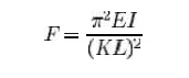
where
F = maximum or critica l force (vertical load
on column), E = modulus of elasticit y,
I =
area moment of inertia,
L =
unsupported length of column,
K = column effective length factor, whose value
depends on the con ditions of end support of the column, as follow s.
For both ends pinned (h
inged, free to rotate), K = 1.0. For both ends fixed, K = 0.50.
For one end fixed and t he other end pinned, K
= 0.699....
For one end fixed and t he
other end free to move laterally, K = 2.0. KL is the effective
lengtth of the column.
Examination
of this formula reveals the following interesting facts with regard to the
load-bearing ability of slender colum ns.
1.
Elasticity and
not compressive strength of the materials of the column determines the critical
load.
2.
The critical load
is directly proportional to the second moment of area of the cross section.
3. The boundary conditio ns have a considerable effect on the crit ical load of slender columns. The boundary conditions determine the mode of bend ing and the distance between inflection poi nts on the deflected column. The closer to gether the inflection points are, the higher the resulting capacity of the column.
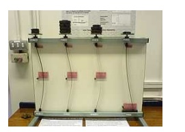
A demonstration model
illustra ting the different "Euler" buckling modes. The model shows
how the boundary conditions affect the critical load of a slender column.
Notice that each of the columns are identical, apart from the boundary
conditions.
The
strength of a column may t herefore be increased by distributing the material
so as to increase the moment of inertia. This can be done without increasing
the weigh t of the column by distributing the material as fa r from the
principal axis of the cross secti on as possible, while keeping the material
thick eno ugh to prevent local buckling. This bears ou t the well-known fact
that a tubular section is much m ore efficient than a solid section for column
service.
Another
bit of information th at may be gleaned from this equation is the effect of
length on critical load. For a given size column, doubling the unsupported
length quarters the allowable load. The restraint offered by t he end
connections of a column also affects the critical load. If the connections are
perfectly rigidd, the critical load will be four times that for a similar
column where there is no resistance to rotation (hinged at the ends).
Since the moment of inertia of a surface is
its area multiplied by the square of a length called the radius of gyration,
the above fo rmula may be rearranged as follows. Using the Euler formula for
hinged ends, and substituting A �r2 for I, the following formula
results.
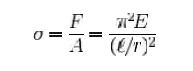
where F / A is
the allowable stress of the column, and l / r is the slenderness
ratio.
Since structural columns are c ommonly of
intermediate length, and it is im possible to obtain an ideal column, the Euler
formula on its own has little practical application for ordinary design. Issues
that cause deviation f rom the pure Euler strut behaviour inclu de
imperfections in geometry in combination with plasticity/non-linear stress
strain behaviour of the column's material. Consequently, a number of empirical
column formulae have been developed to agree with test data, all of which
embody the slenderness ratio. For design, appropriate safety factors are
introduced into these formulae. One such formular is the Perry Robertson
formula which estimates of the critical buckling load based on an initial (
small) curvature. The Rankine Gordon fomular is als o based on eperimental
results and surgests t hat a strut will buckle at a load Fmax given by:
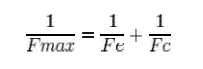
where
Fe is the euler maximum load and Fc is the maximum compresivee load. This
formular typically produces a conservative estimate of Fmax.
Self-buckling
A free-standing, vertical colummn, with
density ?, Young's modulus E, and radius r, will buckle under its
own weight if its height exceeds a certain critical height:
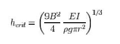
where g is the
acceleration due to gravity, I is the second moment of ar ea of the beam
cross section, and B is the first zero o f the Bessel function of the
first kind of orde r -1/3, which is equal to 1.86635...
Slenderness ratio
Euler's
Theory : The struts w hich fail by
buckling can be analyzed by Euler's theory. In the following sections,
different ca ses of the struts have been analyzed.
Case A: Strut
with pinned en ds:
Consider an axially loaded stru t, shown below, and is subjected to an
axial load �P' this load �P' produces a deflection �y' at a distance �x' from
one end. Assume that the ends are either pin
jointed or rounded so that
there is no moment at either end.
Assumption:
The
strut is assumed to be initially straight, the end load being applied axially
through centroid.
In this equation �M' is not a fu nction �x'. Therefore this equation can
not be integrated directly as has been
done in the case of de flection of beams by integration method.
Though this equation is in �y ' but we can't say at this stage where the
deflection would be maximum
or minimum.
So the above differential
equation can be arranged in the following form
Let us define a operator
D = d/dx
(D2 + n2) y =0 where n2 =
P/EI
This
is a second order differ ential equation which has a solution of the form
consisting of complimentary function and particular integral but for the time
being we are interested in the complementary solution only[i n this P.I = 0;
since the R.H.S of Diff. equatio n = 0]
Thus y = A cos (nx) + B sin (nxx)
Where A and B are some
constants.
Therefore
In order to evaluate the
constants A and B let us apply the boundary conditions,
(i) at x = 0; y = 0
(ii) at x = L ; y = 0
Applying the first boundary
condition yields A = 0.
Applying the second boundary
condition gives
From
the above relationship the least value of P which will cause the strut to
buckle, and it is called the " Euler Crippling Load " Pe from
which w obtain.
The
interpretation of the above analysis is that for all the values of the load P,
other than those which make sin nL = 0; the strut will remain perfectly
straight since
y = B sin nL = 0
For the particular value of
Then
we say that the strut is in a state of neutral equilibrium, and theoretically
any deflection which it suffers will be maintained. This is subjected to the limitation that �L' remains sensibly
constant
and in practice slight increase in load at the critical value will cause the
deflection to increase appreciably until the material fails by yielding.
Further
it should be noted that the deflection is not proportional to load, and this
applies to all strut problems; like wise it will be found that the maximum
stress is not proportional to load.
The
solution chosen of nL = p is just one particular solution; the solutions nL=
2p, 3p, 5p etc are equally valid mathematically and they do, infact, produce values of �Pe' which are
equally valid
for
modes of buckling of strut different from that of a simple bow. Theoretically
therefore, there are an infinite number of values of Pe , each corresponding
with a different mode of buckling.
The
value selected above is so called the fundamental mode value and is the lowest
critical load producing the single bow buckling condition.
The solution nL = 2p produces
buckling in two half - waves, 3p in three half-waves etc.
If load is applied sufficiently quickly to
the strut, then it is possible to pass through the fundamental mode and to
achieve at least one of the other modes which are theoretically possible. In
practical loading situations, however, this is rarely achieved since the high
stress associated with the first critical condition generally ensures immediate
collapse.
Related Topics