Chapter: Electrical Drives & Control : Drive Motor Characteristics
DC Shunt Motors: Characteristics, Electric Braking
DC SHUNT MOTORS
1. CHARACTERISTICS OF DC SHUNT MOTOR
1. Electrical characteristics
Torque / Armature current characteristics
Speed / Armature current characteristics
2. Mechanical characteristics
Speed / Torque characteristics
Characteristics of dc shunt motor

Torque vs Armature current characteristics.
The torque developed by the dc motor
T α Ia
In case of dc shunt motors the field excitation current is constant and supply voltage is kept constant. Therefore flux per pole will be constant.
T α Ia
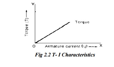
Therefore torque developed in a dc shunt motor will be directly proportional to the armature current. The graph representing the variation of torque with armature current.
Speed/Armature current characteristics
The back emf equation for dc motor is
Eb = PNZ /60A = V– Ia Ra
Therefore
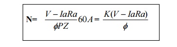
Where K = 60A/ ZP and it is constant.
In dc shunt motor, when supply voltage V is kept constant the shunt field current and hence flux per pole will also be constant.
N α V–
The speeds of the dc shunt motor decreases with increase in armature current due to loading.
The graph representing variation of speed with armature current is drooping slightly.
The drop is speed from no load to full load will be about 3 to 6 percent.
But the armature reaction effect weakens the field on load and tends to oppose drop in speed so
so that the rarely drops by more than about 5 percent from no load to full load.
Therefore shunt motor is considered as constant speed motor.
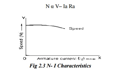
Speed vs Torque characteristics:
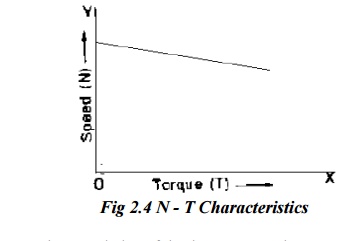
Ø From the above two characteristics of dc shunt motor, the torque developed and speed at various armature currents of dc shunt motor may be noted.
Ø If these values are plotted, the graph representing the variation of speed with torque developed is obtained.
This curve resembles the speed Vs current characteristics as the torque is directly proportional to the armature current.
2. ELECTRIC BRAKING IN DC SHUNT MOTOR
There are three types of electric braking namely,
1. Rheostatic or Dynamic braking
2. Plugging or counter current braking or reverse current braking
3. Regenerative braking
Electric braking of DC shunt motors
A. Rheostatic braking
In this method of braking, the armature is disconnected from the supply and is connected across a variable resistance R.
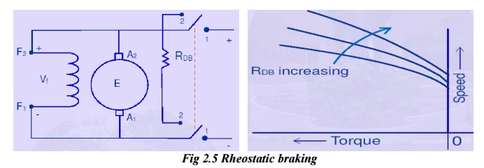
The field winding is left connected across the supply and it is undisturbed.
The braking effect is controlled by varying the series resistance R.
Speed-torque characteristics under dynamic braking
· It will be a straight line through the origin in the second quadrant .
· In the first quadrant ,the curve shows that the motor is operating steadily for a given load torque TL at the point A on its natural characteristics.
· The speed no represents ideal no load speed.
· Due to braking the operating point shifts to point B on the characteristics in the II quadrant from point A.
· The motor then decelerates along B O to stand still condition.
· The slope of the braking characteristics in II quadrant can be controlled by varying the braking resistor R.
· Hence, any braking time can be obtained by proper choice of the braking resistor R.
B. Plugging (or) Counter current braking
In this method of breaking, connections to the armature terminals are reversed so that motor tends to run in the opposite direction.
Due to the reversal of armature connections, both V and Eb start acting in the same direction around the circuit.
In order to limit the armature current to a safe value, it is essential to insert a resistor in the circuit while reversing the armature connections.
When compared with rheostat braking, plugging gives better braking torque.
This method is commonly used for Printing presses, elevators, rolling mills and machine tools.
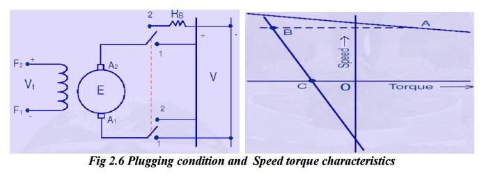
Plugging is executed at a time when the motor is operating at the point E characteristics A for a load torque TL.
Due to plugging, the operating point shifts to point F on characteristics B as the speed of the motor cannot change instantaneously due to inertia.
Due to braking torque developed ,the motor decelerates along the characteristics B until the motor stops at GwHEN reversal of rotation is not required, the supply must be switched off when the motor speed becomes very near to zero.
If the supply is not switched off,the motor will gain speed in the opposite direction along GH on characteristics B .as soon as the direction of the rotation is reversed ,the induced emf in the armature changes its polarity and again acts against the applied voltage so that the drive will rotate in the reverse direction under motoring condition.
At point H,additional resistance are cut out from the armature circuit and hence the operating point shifts to point I on the natural characteristics C for a load torque,TL
If plugging is executed again at the point J,then braking and acceleration in the forward direction will corresponded to J –K-L-M-E.
C. Regenerative braking
This method is used when the load on the motor has overhauling characteristics as in the lowering of the case of a hoist or downgrade motion of electric train.
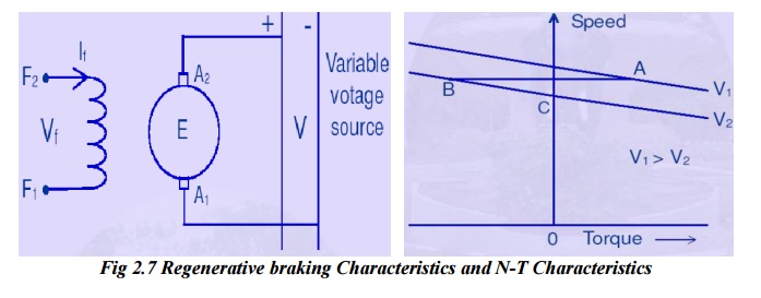
§ Regenerative takes place when Eb becomes greater than V.this happens when the overhauling load acts as a prime mover and so drives the machine asa generator.
§ Hence ,the direction of Ia and armature torque is reversed and speed falls until eb becomes less than V.
§ During slowing down of the motor ,power is returned to the line which may be used for supplying another train on an upgrade motion there by essential to have some type of mechanical braking also in order to hold the load in the event of power failure.
§ At zero torque characteristics passes through the point corresponding to ideal no load speed, no as in the case of motoring.
§ From the characteristics curves, it is clear that, higher the armature circuit resistance ,the higher is the speed at which the motor has to run for a given braking torque.
Related Topics