Chapter: Optical Communication and Networking : Introduction
Cylindrical fiber: Modes, Mode coupling, Step and Graded index fibers
Cylindrical fiber
1. Modes
The exact solution of Maxwell’s equations for a cylindrical homogeneous core dielectric waveguide* involves much algebra and yields a complex result. Although the presentation of thismathematics is beyond the scope of this text, it is useful to consider the resulting modal fields. In common with the planar guide (Section 1.3.2), TE (where Ez = 0) and TM (where Hz = 0) modes are obtained within the dielectric cylinder. The cylindrical waveguide, however, is bounded in two dimensions rather than one. Thus two integers, l and m, are necessary in order to specify the modes, in contrast to the single integer (m) required for the planar guide.
For the cylindrical waveguide we therefore refer to TElm and TMlm modes. These modes correspond to meridional rays (see Section 1.2.1) traveling within the fiber. However, hybrid modes where Ez and Hz are nonzero also occur within the cylindrical waveguide. These modes, which result from skew ray propagation (see Section 1.2.4) within the fiber, are designated HElm and EHlm depending upon whether the components of H or E make the larger contribution to the transverse (to the fiber axis) field. Thus an exact description of the modal fields in a step index fiber proves somewhat complicated.
Fortunately, the analysis may be simplified when considering optical fibers for com-munication purposes. These fibers satisfy the weakly guiding approximation where the relative index difference Δ1. This corresponds to small grazing angles θ in Eq. (1.34). In fact is usually less than 0.03 (3%) for optical communications fibers. For weakly guiding structures with dominant forward propagation, mode theory gives dominant transverse field components. Hence approximate solutions for the full set of HE, EH, TE and TM modes may be given by two linearly polarized components.
These linearly polarized (LP) modes are not exact modes of the fiber except for the fundamental (lowest order) mode. However, as in weakly guiding fibers is very small, then HE– EH mode pairs occur which have almost identical propagation constants. Such modes are said to be degenerate. The superpositions of these degenerating modes characterized by a common propagation constant correspond to particular LP modes regardless of their HE, EH, TE or TM field configurations. This linear combination of degenerate modes obtained from the exact solution produces a useful simplification in the analysis of weakly guiding fibers.
The relationship between the traditional HE, EH, TE and TM mode designations and the LPlm mode designations is shown in Table 1.1. The mode subscripts l and m are related to the electric field intensity profile for a particular LP mode (see Figure 1.11(d)). There are in general 2l field maxima around the circumference of the fiber core and m field maxima along a radius vector. Furthermore, it may be observed from Table 1.1 that the notation for labeling the HE and EH modes has changed from that specified for the exact solution in the cylindrical waveguide mentioned previously.
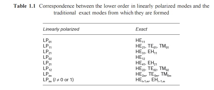
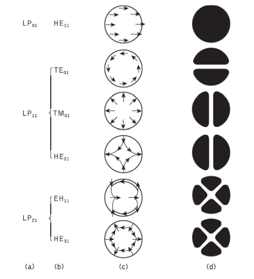
Figure 1.11 The electric field configurations for the three lowest LP modes illustrated in terms oftheir constituent exact modes: (a) LP mode designations; (b) exact mode designations; (c) electric field distribution of the exact modes; (d) intensity distribution of Ex for the exact modes indicating the electric field intensity profile for the corresponding LP modes
The subscript l in the LP notation now corresponds to HE and EH modes with labels l + 1 and l − 1 respectively. The electric field intensity profiles for the lowest three LP modes, together with the electric field distribution of their constituent exact modes, are shown in Figure 1.11.
It may be observed from the field configurations of the exact modes that the field strength in the transverse direction (Ex or Ey) is identical for the modes which belong to the same LP mode.
Hence the origin of the term ‘linearly polarized’.
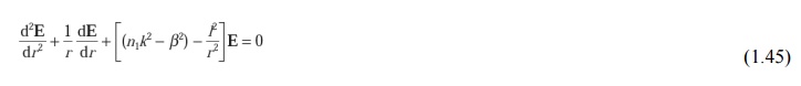
Using Eq. (1.31) for the cylindrical homogeneous core waveguide under the weak guidance conditions outlined above, the scalar wave equation can be written in the form
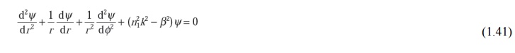
where ψ is the field (E or H), n1 is the refractive index of the fiber core, k is the propagation constant for light in a vacuum, and r and φ are cylindrical coordinates. The propagation constants of the guided modes β lie in the range:

where n2 is the refractive index of the fiber cladding. Solutions of the wave equation for the cylindrical fiber are separable, having the form:
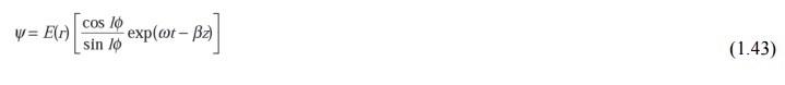
where in this case ψ represents the dominant transverse electric field component. The periodic dependence on φ following coslφ or sin lφ gives a mode of radial order l. Hence the fiber supports a finite number of guided modes of the form of Eq. (1.43).
Introducing the solutions given by Eq. (1.43) into Eq. (1.41) results in a differential equation of the form:
For a step index fiber with a constant refractive index core, Eq. (1.43) is a Bessel differential equation and the solutions are cylinder functions. In the core region the solutions are Bessel functions denoted by Jl.
A graph of these gradually damped oscillatory functions (with respect to r) is shown in Figure 1.12(a). It may be noted that the field is finite at r = 0 and may be represented by the zero-order Bessel function J0. However, the field vanishes as r goes to infinity and the solutions in the cladding are therefore modified Bessel functions denoted by Kl. These modified functions decay exponentially with respect to r, as illustrated in Figure 1.12(b). The electric field may therefore be given by:
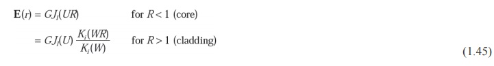
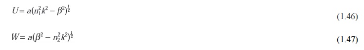
Where G is the amplitude coefficient and R = r/a is the normalized radial coordinate when a is the radius of the fiber core; U and W, which are the eigenvalues in the core and cladding respectively,* are defined as:
2. Mode coupling
We have thus far considered the propagation aspects of perfect dielectric waveguides. However, waveguide perturbations such as deviations of the fiber axis from straightness, variations in the core diameter, irregularities at the core–cladding interface and refractive index variations may change the propagation characteristics of the fiber. These will have the effect of coupling energy traveling in one mode to another depending on the specific perturbation. Ray theory aids the understanding of this phenomenon, as shown in Figure 1.13, which illustrates two types of perturbation. It may be observed that in both cases the ray no longer maintains the same angle with the axis. In electromagnetic wave theory this corres- ponds to a change in the propagating mode for the light. Thus individual modes do not normally propagate throughout the length of the fiber without large energy transfers to adjacent modes, even when the fiber is exceptionally good quality and is not strained or bent by its surroundings. This mode conversion is known as mode coupling or mixing. It is usually analyzed using coupled mode equations which can be obtained directly from Maxwell’s equations.
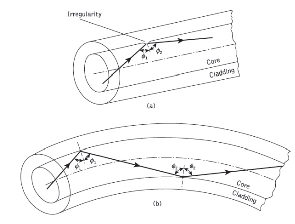
Figure 1.13 Ray theory illustrations showing two of the possible fiber perturbations which give mode coupling: (a) irregularity at the core–cladding interface; (b) fiber bend
3. Step index fibers
The optical fiber considered in the preceding sections with a core of constant refractive index n1 and a cladding of a slightly lower refractive index n2is known as step index fiber. This is because the refractive index profile for this type of fiber makes a step change at the core–cladding interface, as indicated in Figure 1.14, which illustrates the two major types of step index fiber.
The refractive index profile may be defined as:
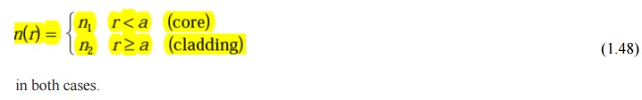
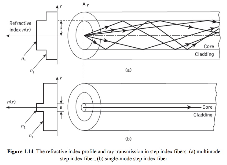
Figure 1.14(a) shows a multimode step index fiber with a core diameter of around 50µm or greater, which is large enough to allow the propagation of many modes within the fiber core. This is illustrated in Figure 1.14(a) by the many different possible ray paths through the fiber. Figure 1.14(b) shows a single-mode or monomode step index fiber which allows the propagation of only one transverse electromagnetic mode (typically HE11), and hence the core diameter must be of the order of 2 to 10µm. The propagation of a single mode is illustrated in Figure 1.14(b) as corresponding to a single ray path only (usually shown as the axial ray) through the fiber.
The single-mode step index fiber has the distinct advantage of low intermodal dispersion (broadening of transmitted light pulses), as only one mode is transmitted, whereas with multimode step index fiber considerable dispersion may occur due to the differing group velocities of the propagating modes. This in turn restricts the maximum bandwidth attainable with multimode step index fibers, especially when com- pared with single-mode fibers. However, for lower bandwidth applications multimode fibers have several advantages over single-mode fibers. These are:
a) The use of spatially incoherent optical sources (e.g. most light-emitting diodes) which cannot be efficiently coupled to single-mode fibers.
b) Larger numerical apertures, as well as core diameters, facilitating easier coupling to optical sources
c) Lower tolerance requirements on fiber connectors
Multimode step index fibers allow the propagation of a finite number of guided modes along the channel. The number of guided modes is dependent upon the physical para- meters (i.e. relative refractive index difference, core radius) of the fiber and the wavelengths of the transmitted light which are included in the normalized frequency V for the fiber. Mode propagation does not entirely cease below cutoff. Modes may propagate as unguided or leaky modes which can travel considerable distances along the fiber. Nevertheless, it is the guided modes which are of paramount importance in optical fiber communications as these are confined to the fiber over its full length. that the total number of guided modes or mode volume Ms for a step index fiber is related to the V value for the fiber by the approximate expression
Which allows an estimate of the number of guided modes propagating in a particular multimode step index fiber.
4. Graded index fibers
Graded index fibers do not have a constant refractive index in the core* but a decreasing core index n(r) with radial distance from a maximum value ofn1 at the axis to a constant value n2 beyond the core radius a in the cladding. This index variation may be represented as:
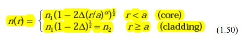
where D is the relative refractive index difference and α is the profile parameter which gives the characteristic refractive index profile of the fiber core. Equation (1.50) which is a convenient method of expressing the refractive index profile of the fiber core as a variation of α, allows representation of the step index profile when α = ∞, a parabolic profile when α = 2 and a triangular profile when α = 1. This range of refractive index profiles is illustrated in Figure 1.15
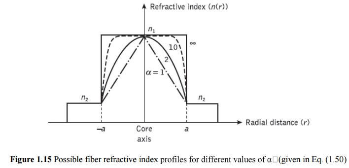
The graded index profiles which at present produce the best results for multimode optical propagation have a near parabolic refractive index profile core with a ~~2. Fibers with such core index profiles are well established and consequently when the term ‘graded index’ is used without qualification it usually refers to a fiber with this profile.
For this reason in this section we consider the waveguiding properties of graded index fiber with a parabolic refractive index profile core.
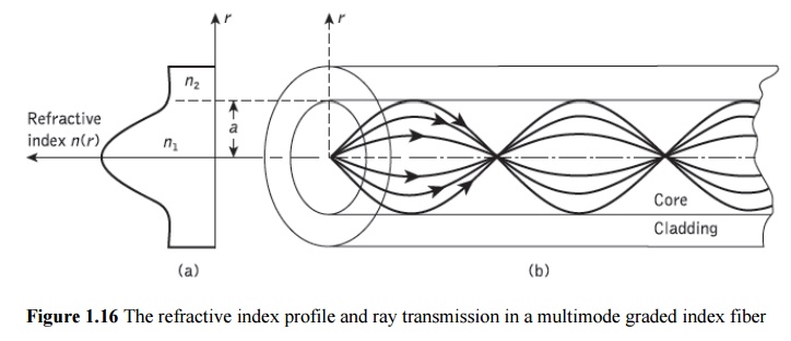
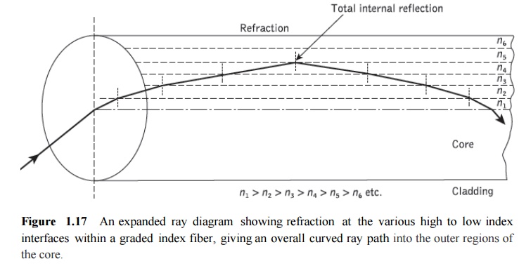
A multimode graded index fiber with a parabolic index profile core is illustrated in Figure 1.16. It may be observed that the meridional rays shown appear to follow curved paths through the fiber core. Using the concepts of geometric optics, the gradual decrease in refractive index from the center of the core creates many refractions of the rays as they are effectively incident on a large number or high to low index interfaces. This mechanism is illustrated in Figure 1.17 where a ray is shown to be gradually curved, with an ever- increasing angle of incidence, until the conditions for total internal reflection are met, and the ray travels back towards the core axis, again being continuously refracted.
Multimode graded index fibers exhibit far less intermodal dispersion than multimode step index fibers due to their refractive index profile. Although many different modes are excited in the graded index fiber, the different group velocities of the modes tend to be normalized by the index grading. Again considering ray theory, the rays traveling close to the fiber axis have shorter paths when compared with rays which travel
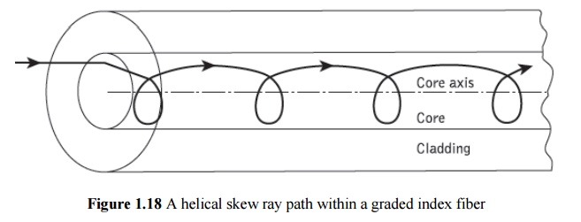
However, the near axial rays are transmitted through a region of higher refractive index and therefore travel with a lower velocity than the more extreme rays. This compensates for the shorter path lengths and reduces dispersion in the fiber. A similar situation exists for skew rays which follow longer helical paths, as illus- trated in Figure 1.18. These travel for the most part in the lower index region at greater speeds, thus giving the samemechanism of mode transit time equalization. Hence, multi- mode graded index fibers with parabolic or near-parabolic index profile cores have trans- mission bandwidths which may be orders of magnitude greater than multimode step index fiber bandwidths. Consequently, although they are not capable of the bandwidths attain- able with single-mode fibers, such multimode graded index fibers have the advantage of large core diameters (greater than 30 µm) coupled with bandwidths suitable for long- distance communication.
The parameters defined for step index fibers (i.e. NA, Δ, V ) may be applied to graded index fibers and give a comparison between the two fiber types. However, it must be noted that for graded index fibers the situation is more complicated since the numerical aperture is a function of the radial distance from the fiber axis. Graded index fibers, therefore, accept less light than corresponding step index fibers with the same relative refractive index difference.
Related Topics