Chapter: Embedded Systems Design : Interfacing to the analogue world
Codecs: Linear, A-law and Inf-law, DPCM and ADPCM
Codecs
So far the discussion has been based on analogue to digital (A to D) and
digital to analogue (D to A) converters. These are the names used for generic
converters. Where both A to D and D to A conversion is supported, they can also
be called codecs. This name is derived from coder-decoder and is
usually coupled with the algorithm that is used to perform the coding. Generic
A to D conversion is only one form of coding; many others are used within the
industry where the analogue signal is converted to the digital domain and then
encoded using a different technique. Such codecs are often prefixed by the
algorithm used for the encoding.
Linear
A linear codec is one that is the same as the standard A to D and D to A
converters so far described, i.e. the relationship between the analogue input
signal and the digital representation is linear. The quantisation step is the
same throughout the range and thus the increase in the analogue value necessary
to increment the digital value by one is the same, irrespective of the analogue
or digital values. Linear codecs are frequently used for digital audio.
A-law and µ-law
For telecommunications applications with a limited band-width of 300 to
3100 Hz, logarithmic codecs are used to help improve quality. These codecs,
which provide an 8 bit sample at 8 kHz, are used in telephones and related
equipment. Two types are in common use: the a-law codec in the UK and the µ-law
codec in the US. By using a logarithmic curve for the quantisation, where the
analogue increase to increment the digital value varies de-pending on the size
of the analogue signal, more digital bits can be allocated to the more
important parts of the analogue signal and thus improve their resolution. The
less important areas are given less bits and, despite having coarser
resolution, the quality reduc-tion is not really noticeable because of the
small part they contrib-ute to the signal. Conversion between a linear digital
signal and a law/µ-law or between an a-law and µ-law signal is easily per-formed
using a look-up table.
PCM
The linear codecs that have been so far described are also known as PCM
— pulse code modulation codecs. This comes from the technique used to
reconstitute the analogue signal by supply-ing a series of pulses whose
amplitude is determined by the digital value. This term is frequently used
within the telecommunications industry.
There are alternative ways of encoding using PCM which can reduce the
amount of data needed or improve the resolution and accuracy.
DPCM
Differential pulse coded modulation (DPCM) is similar to PCM, except
that the value encoded is the difference between the current sample and the
previous sample. This can improve the accuracy and resolution by having a 16
bit digital dynamic range without having to encode 16 bit samples. It works by
increasing the dynamic range and defining the differential dynamic range as a
partial value of it. By encoding the difference, the smaller digital value is
not exceeded but the overall value can be far greater. There is one proviso:
the change in the analogue value from one sample to another must be less than
the differential range and this deter-mines the maximum slope of any waveform
that is encoded. If the range is exceeded, errors are introduced.
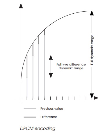
The diagram shows how this encoding works. The ana-logue value is
sampled and the previous value subtracted. The result is then encoded using the
required sample size and allowing for a plus and minus value. With an 8 bit
sample size, 1 bit is used as a sign bit and the remaining 7 bits are used to
encode data. This allows the previous value to be used as a reference, even if
the next value is smaller. The 8 bits are then stored or incorporated into a
bitstream as with a PCM conversion.
To decode the data, the reverse operation is performed. The signed
sample is added to the previous value, giving the correct digital value for
decoding. In both the decode and encode process, values which are far larger
than the 8 bit sample are stored. This type of encoding is easily performed
with a microprocessor with 8 bit data and a 16 bit or larger accumulator.
A to D and D to A converters do not have to cope with the full
resolution and can simply be 8 bit decoders. These can be used provided
analogue subtractors and adders are used in conjunction with them. The
subtractor is used to reduce the analogue input value before inputting to the
small A to D converter. The adder is used to create the final analogue output
from the previous ana-logue value and the output from the D to A converter.
ADPCM
Adaptive differential pulse code modulation (ADPCM) is a variation on
the previous technique and frequently used in tel-ecommunications. The
difference is encoded as before but instead of using all the bits to encode the
difference, some bits are used to encode the quantisation value that was used
to encode the data. This means that the resolution of the difference can be
adjusted — adapted — as needed and, by using non-linear quantisation values,
better resolution can be achieved and a larger dynamic range supported.
Related Topics