Chapter: Mechanical : Unconventional machining process : Thermal Energy Based Processes
Thermal Energy Based Processes
THERMAL ENERGY BASED PROCESSES
· Laser–Beam Machining (LBM)
Electron
Beam Machinin g (EBM)
· Plasma Arc Machining (PAM)
1. Laser–Beam Machining
Laser-beam
machining i s a thermal material-removal process that utilizes a high-energy,
Coherent light beam to melt and vaporize particles on the surface of metallic
and non-metallic work pieces. Lasers can be ussed to cut, drill, weld and mark.
LBM is particularly suitable for making accurately placed hol es. A schematic
of laser beam machining is s hown in Figure
Different types of lasers are a
vailable for manufacturing operations which are as follows:
• CO2 (pulsed or continuous wave): It
is a gas laser that emits light in the infrared region. It can provide up to 25
kW in continuous-wave mode.
•
Nd:YAG:
Neodymium -doped Yttrium-Aluminum-Garnet (Y3Al5O 12) laser is a solid- state
laser which can deliver light through a fibre-optic cable. It c an provide up
to 50 kW power in pulsed m ode and 1 kW in continuous-wave mode.
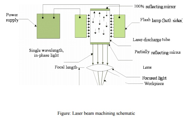
Figure: Laser beam machining
schematic
Applications
LBM can make very accurate holes as
small as 0.005 mm in refractory metals ceramics, and composite material without
warping the work pieces. This process is used widely for drilling
Laser beam cutting (drilling)
•
In
drilling, energy transferred (e.g., via Nd YAG laser) into the workpiece melts
the material at the point of contact, which subsequently changes into a plasma
and leaves the region.
•
A
gas jet (typically, oxygen) can further facilitate this phase transformation
and departure of material removed.
•
Laser
drilling should be targeted for hard materials and hole geometries that are
difficult to achieve with other methods.
A typical SEM micrograph hole
drilled by laser beam machining process employed in making a hole is shown in
Figure
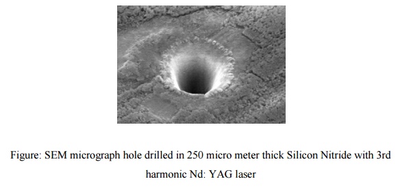
Figure:
SEM micrograph hole drilled in 250 micro meter thick Silicon Nitride with 3rd
harmonic Nd: YAG laser
2
Laser beam cutting (milling)
•
A
laser spot reflected onto the surface of a workpiece travels along a prescribed
trajectory and cuts into the material.
•
Continuous-wave
mode (CO2) gas lasers are very suitable for laser cutting providing
High-average power, yielding high material-removal rates, and smooth cutting
surfaces
Advantage of laser cutting
•
No
limit to cutting path as the laser point can move any path.
•
The
process is stress less allowing very fragile materials to be laser cut without
any support.
•
Very
hard and abrasive material can be cut.
•
Sticky
materials are also can be cut by this process.
•
It
is a cost effective and flexible process.
•
High
accuracy parts can be machined.
•
No
cutting lubricants required
•
No
tool wear
•
Narrow
heat effected zone
Limitations of laser cutting
•
Uneconomic
on high volumes compared to stamping
•
Limitations
on thickness due to taper
•
High
capital cost
•
High
maintenance cost
•
Assist
or cover gas required
3
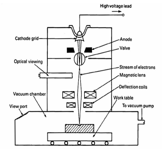
ELECTRON BEAM MACHINING (EBM)
As
has already been mentioned in EBM the gun is operated in pulse mode. This is
achieved by appropriately biasing the biased grid located just after the
cathode. Switching pulses are given to the bias grid so as to achieve pulse
duration of as low as 50 μs to as long as 15 ms. Beam current is directly
related to the number of electrons emitted by the cathode or available in the
beam. Beam current once again can be as low as 200 μamp to 1 amp. Increasing
the beam current directly increases the energy per pulse. Similarly increase in
pulse duration also enhances energy per pulse. High-energy pulses (in excess of
100 J/pulse) can machine larger holes on thicker plates. The energy density and
power density is governed by energy per pulse duration and spot size. Spot
size, on the other hand is controlled by the degree of focusing achieved by the
electromagnetic lenses. A higher energy density, i.e., for a lower spot size,
the material removal would be faster though the size of the hole would be
smaller. The plane of focusing would be on the surface of the work piece or
just below the surface of the work piece.
1. Electrons generated in a vacuum
chamber
2. Similar to cathode ray tube
3. Electron gun
4. Cathode - tungsten filament at 2500
– 3000 degC
5. Emission current – between 25 and
100mA (a measure of electron beam density)
MRR:
In the region where the beam of
electrons meets the workpiece, their energy is converted Into heat
Workpiece surface is melted by a
combination of electron pressure and surface tension Melted liquid is rapidly
ejected and vaporized to effect material removal
Temperature of the workpiece
specimen outside the region being machined is reduced by pulsing the electron
beam (10 kHz or less)
Advantages
of Ebm:
1. Large
depth-to-width ratio of material penetrated
by the beam with applications of very fine hole drilling becoming feasible
2. There
are a minimum nu mber of pulses ne associated
with an optimum accelerating Voltage. In practice the number of pulses to
produce a given hole depth is usually
found to decrease with increase in accelerating voltage.
4.
PLASMA ARC MACHINING (PAM)
The
plasma welding process was introduced to the welding industry in 1964 as a
method of bringing better control to the a rc welding process in lower current
ranges. Todday, plasma retains the original advantages it brought to industry
by providing an advanced level of control and accuracy to produce high quality
welds in miniature or precision applications and to provide long electrode life
for high production requirements.
The plasma process is equally suited
to manual and automatic applications. It has been used in a variety of
operations ranging from high volume welding of strip met al, to precision
welding of surgical instruments, to automatic repair of jet engine blades, to
the manual welding of kitchen equipment for the food and dairy industry.
5. PLASMA ARC WELDING (PAW):
Plasma arc welding (PAW) is a
process of joining of metals, produced by heating with a constricted arc
between an electrode and the work piece (transfer arc) or the electrode and the
constricting nozzle (non transfer arc). Shielding is obtained from the hot
ionized gas issuing from the orifice, which may be supplemented by an auxiliary
source of shielding gas. Transferred arc process produces plasma jet of high
energy density and may be used for high speed welding and cutting of Ceramics,
steels, Aluminum alloys, Copper alloys, Titanium alloys, Nickel alloys.
Non-transferred arc process produces
plasma of relatively low energy density. It is used for welding of various
metals and for plasma spraying (coating).
Equipment:
(1) Power source. A constant current
drooping characteristic power source supplying the dc Welding current is
required. It should have an open circuit voltage of 80 volts and have a duty
cycle of 60 percent.
(2) Welding torch. The welding torch for
plasma arc welding is similar in appearance to a gas tungsten arc torch but it
is more complex.
(a) All plasma torches are water cooled,
even the lowest-current range torch. This is because the arc is contained
inside a chamber in the torch where it generates considerable heat.During the
non transferred period, the arc will be struck between the nozzle or tip with the
orifice and the tungsten electrode.
(b) The torch utilizes the 2 percent
thoriated tungsten electrode similar to that used for gas tungsten welding.
(3) Control console. A control
console is required for plasma arc welding. The plasma arc torches are designed
to connect to the control console rather than the power source. The console
includes a power source for the pilot arc, delay timing systems for
transferring from the pilot arc to the transferred arc, and water and gas
valves and separate flow meters for the plasma gas and the shielding gas. The
console is usually connected to the power source. The high-frequency generator
is used to initiate the pilot arc.
Principles
of Operation:
The plasma arc welding process is
normally compared to the gas tungsten arc process. But in the TIG-process, the
arc is burning free and unhandled, whereas in the plasma-arc system, the arc is
necked by an additional water-cooled plasma-nozzle. A plasma gas – almost
always 100 % argon –flows between the tungsten electrode and the plasma nozzle.
The welding process involves heating
a gas called plasma to an extremely high temperature and then ionizing it such
that it becomes electrically conductive. The plasma is used to transfer an
electric arc called pilot arc to a work piece which burns between the tungsten
electrode and the plasma nozzle. By forcing the plasma gas and arc through a
constricted orifice the metal, which is to be welded is melted by the extreme
heat of the arc. The weld pool is protected by the shielding gas, flowing
between the outer shielding gas nozzle and the plasma nozzle. As shielding gas
pure argon-rich gas-mixtures with hydrogen or helium are used.
The high temperature of the plasma
or constricted arc and the high velocity plasma jet provide an increased heat
transfer rate over gas tungsten arc welding when using the same current. This
results in faster welding speeds and deeper weld penetration. This method of
operation is used for welding extremely thin material and for welding multi
pass groove and welds and fillet welds.
Uses
& Applications:
Plasma arc welding machine is used
for several purposes and in various fields. The common application areas of the
machine are:
1. Single runs autogenous and multi-run
circumferential pipe welding.
2. In tube mill applications.
3. Welding cryogenic, aerospace and
high temperature corrosion resistant alloys.
4. Nuclear submarine pipe system
(non-nuclear sections, sub assemblies).
5. Welding steel rocket motor cases.
6. Welding of stainless steel tubes
(thickness 2.6 to 6.3 mm).
7. Welding of carbon steel, stainless
steel, nickel, copper, brass, monel, inconel, aluminium, titanium, etc.
8. Welding titanium plates up to 8 mm
thickness.
9. Welding nickel and high nickel
alloys.
10.
Melting,
high melting point metals.
11.
Plasma
torch can be applied to spraying, welding and cutting of difficult to cut
metals and alloys.
6
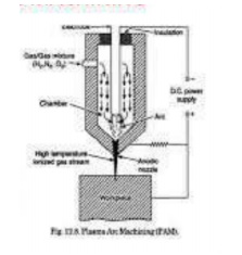
Plasma Arc Machining (PAM):
Plasma-arc machining (PAM) employs a
high-velocity jet of high-temperature gas to melt and displace material in its
path called PAM, this is a method of cutting metal with a plasma-arc, or
tungsten inert-gas-arc, torch. The torch produces a high velocity jet of
high-temperature ionized gas called plasma that cuts by melting and removing
material from the work piece. Temperatures in the plasma zone range from
20,000° to 50,000° F (11,000° to 28,000° C). It is used as an alternative to
oxyfuel-gas cutting, employing an electric arc at very high temperatures to
melt and vaporize the metal.
Equipment:
A plasma arc cutting torch has four
components:
1. The electrode carries the negative
charge from the power supply.
2. The swirl ring spins the plasma gas
to create a swirling flow pattern.
3. The nozzle constricts the gas flow
and increases the arc energy density.
4. The shield channels the flow of
shielding gas and protects the nozzle from metal spatter.
Principle
of operation:
PAM is a thermal cutting process
that uses a constricted jet of high-temperature plasma gas to melt and separate
metal. The plasma arc is formed between a negatively charged electrode inside
the torch and a positively charged work piece. Heat from the transferred arc
rapidly melts the metal, and the high-velocity gas jet expels the molten
material from the cut.
Applications:
The materials cut by PAM are
generally those that are difficult to cut by any other means, such as stainless
steels and aluminum alloys. It has an accuracy of about 0.008".
Related Topics