Chapter: Electrical and electronics : Circuit Theory : Analysing Three Phase Circuits
Star connection and Star connection
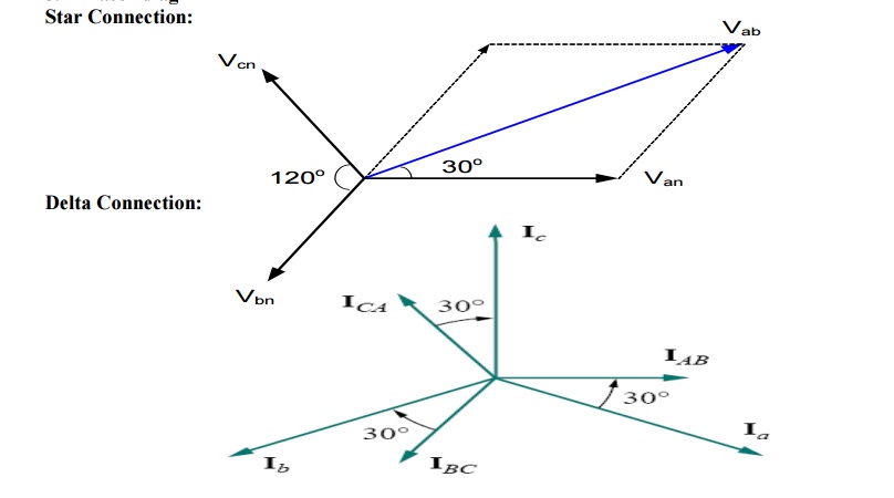
Phasor diagram of three phase supply:
Star Connection:
Connection of Three phases supply:
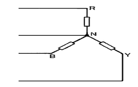
1 Star connection:
a. The terminals R, Y and B are connected together to form the star point, also called the neutral
(N).
b.The lines R, Y and B are connected to the load. If the neutral is connected to the neutral of the load.
Line Voltage:
The voltage between the any two lines is called line voltage.
The voltage between the line and neutral point is called phase voltage.
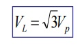
Relation between the line voltage and phase voltage:
Line current:
o The current through the line is called line current.
Phase current:
o The current through in any phase winding is called Phase current.
Relation between the line current and phase current:
IL=IPH
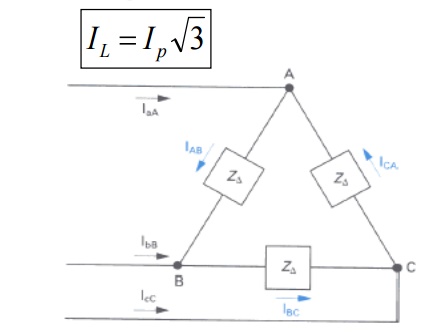
i. Delta Connection:
1) The end of the one winding R is connected to the start of the next phase winding Y. this connection form delta or mesh connection.
Relation between the line voltage and phase voltage:
VL=VPH
Relation between the line current and phase current:
ii. Comparison of star and delta connection:
ü Loads connected in delta dissipate three times more power than when connected in star to the same supply.
ü For the same power, the phase currents must be the same for both delta and star connections (since power=3I p2Rp), hence the line current in the delta connected system is greater than the line current in the corresponding star-connected system.
ü To achieve the same phase current in a star-connected system as in a delta-connected system, the line voltage in the star system is √ 3 times the line voltage in the delta system.
ü Thus for a given power transfer, a delta system is associated with larger line currents (and thus larger conductor cross sectional area) and a star system is associated with a larger line voltage (and thus greater insulation).
b. Three phase balanced and unbalanced voltage sources:
i. Balanced Voltage Sources:
5) If the voltage source have the same amplitude and frequency ω and are out of phase with each other by 120o, the voltage are said to be balanced
ii. Unbalanced Voltage Sources:
6) If the voltage source have the different amplitude and frequency ω and are out of phase with each other by 120o, the voltage are said to be balanced
iii. Balanced load:
7) A balanced load is one in which the phase impedances are equal in magnitude and in phase
iv. Unbalanced load:
8) An unbalanced load is one in which the phase impedances are different in magnitude and phases.
1. Types of Unbalanced load:
9) Unbalanced 3 wire star connected load
10) Unbalanced 4 wire star connected load
11) Unbalanced 3 wire delta connected load
b. Analysis of 3phase 3 wire with star & delta connected loads:
i. Star Connected load:
Consider a Y-connected load. We will derive the relationships of voltage, current and power for this connection.
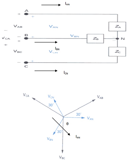
Fig. Three phase Y-connection and phasor diagram
Assume that we are given the phase voltages (sequence ABC):
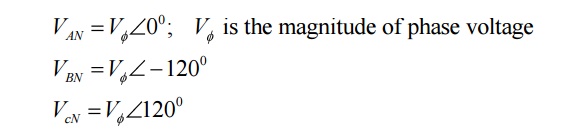
We want to find the line voltages VAB, VBC and VCA.
Using KVL,
VAB = VAN+VNBNB
= VAN - VBN
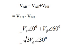
This can be seen in the phasor diagram. Similarly, you can find the other line voltages as,
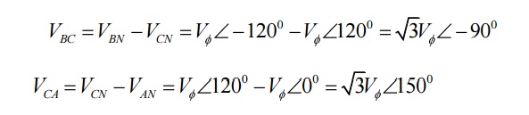
See the phasor diagram above.
For the Y-connected three phase system, we observe that:
Line voltage =√3 Phase Voltage
Line current, IL = Phase current, Iφ
Line voltage VAB is ahead of phase voltage VAN by 300
Total power, PT = 3 Power per phase
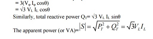
Note: The power factor angle θ is the angle between phase voltage VAN and phase current IAN.
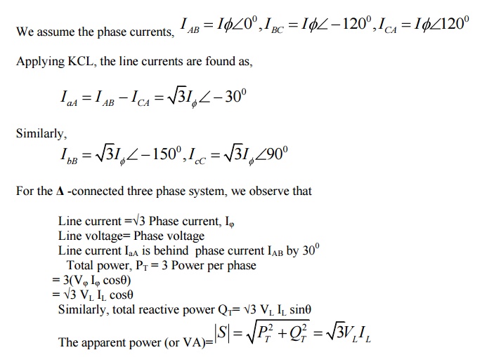
2. Delta connected load:
Consider now a -connected load. The circuit connection and phasor diagram showing the voltages and currents for the balanced circuit is shown below.
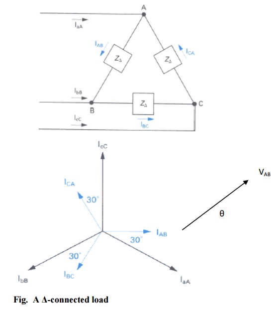
Note again: The power factor angle θ is the angle between phase voltage VAB and phase current IAB.
c. Measurements of power & power factor in 3phase circuits:
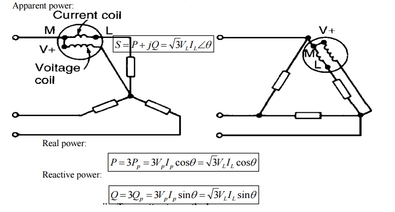
ii. Two wattmeter method
The connection and phasor diagram are shown for an assumed abc phase sequence and lagging power factor.
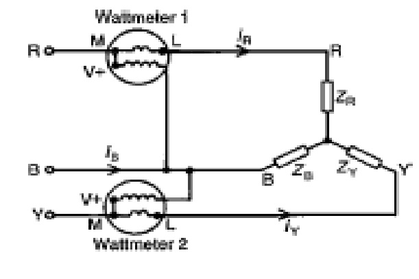
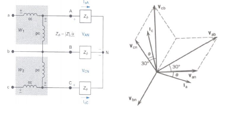
Fig. Two-wattmeter method- connection diagram and phasor diagram
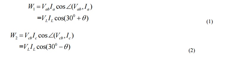
The watt-meter readings are given by,
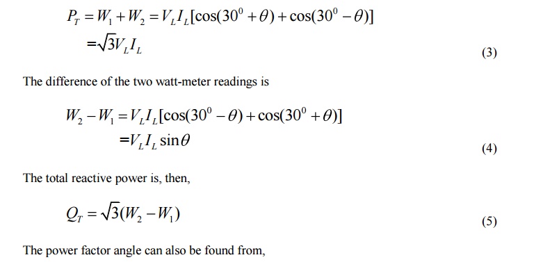
The sum of the two watt-meter readings gives the total three phase power,
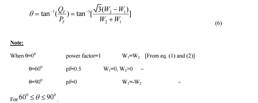
one of the watt-meters will give negative readings. In the laboratory, when you have made the proper watt-meter connections, you will observe that one of the watt-meters is trying to read backwards. After switching the power supply off, reverse the connection of the voltage coil or the current coil (not both). The meter will now read upscale. Assign a negative sign to this reading.
Advantages of Two wattmeter method:
1. The method is applicable for balanced as well as unbalanced loads.
2. Only two wattmeter sufficient to measure total 3 phase power.
3. If the load is balanced not only the power but power factor also can be determined. Disadvantages:
1. Not applicable for 3 phases, 4 wire system.
2. The sign of w1 & w2 must be identified and noted down correctly otherwise it may lead to the wrong result.
Related Topics