Chapter: Flexible Alternating Current Transmission System : Static VAR Compensator (SVC) and Application
SVC Applications
SVC APPLICATIONS
1. Introduction
Static var compensators (SVCs) constitute a mature technology that is finding widespread usage in modern power systems for load compensation as well as transmission-line applications. In high-power networks, SVCs are used for voltage control and for attaining several other objectives such as damping and stability control.
2. Enhancement of Transient Stability
2.1Power-angle curves
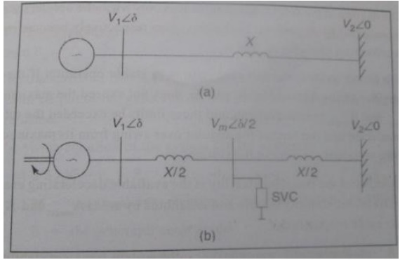
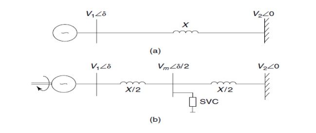
The SMIB system: (a) an uncompensated system (b) an SVC-compensated system
Ø An enhancement in transient stability is achieved primarily through voltage control exercised by the SVC at the interconnected bus.
Ø A simple understanding of this aspect can be obtained from the power-angle curves, of the uncompensated and midpoint SVC–compensated SMIB system.
Ø Consider both the uncompensated and SVC-compensated power system depicted in Fig.
Ø Assume that both systems are transmitting the same level of power and are subject to an identical fault at the generator terminals for an equal length of time.
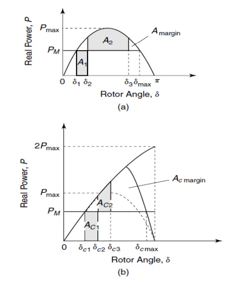
Ø The power-angle curves for both systems are depicted in Fig.
Ø The initial operating point in the uncompensated and compensated systems are indicated by rotor angles d1 and dc1. These points correspond to the intersection between the respective power-angle curves with the mechanical input line PM, which is same for both the cases.
Ø In the event of a 3-phase-to-ground fault at the generator terminals, even though the short-circuit current increases enormously, the active-power output from the generator reduces to zero. Because the mechanical input remains unchanged, the generator accelerates until fault clearing, by which time the rotor angle has reached values d2 and dC2 and the accelerating energy, A1 andAC1, has been accumulated in the uncompensated and compensated system, respectively.
Ø When the fault is isolated, the electrical power exceeds the mechanical input power, and the generator starts decelerating.
Ø The rotor angle, however, continues to increase until δ3 and δc3 from the stored kinetic energy in the rotor.
Ø The decline in the rotor angle commences only when the decelerating energies represented by A2 and AC2 in the two cases, respectively, become equal to the accelerating energies A1 and AC1.
Ø The power system in each case returns to stable operation if the post-fault angular swing, denoted by d3 and dC3, does not exceed the maximum limit of dmax and dc max, respectively. Should these limits be exceeded, the rotor will not decelerate.
Ø The farther the angular overswing from its maximum limit, the more transient stability in the system.
Ø An index of the transient stability is the available decelerating energy, termed the transient-stability margin, and is denoted by areas Amargin and Ac margin in the two cases, respectively. Clearly, as Ac margin significantly exceeds Amargin, the system-transient stability is greatly enhanced by the installation of an SVC. The increase in transient stability is thus obtained by the enhancement of the steady-state power-transfer limit provided by the voltage-control operation of the midline SVC.
2.2 Synchronizing Torque
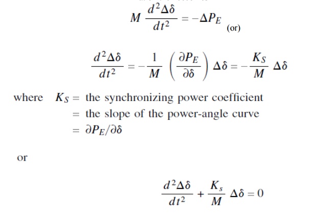
A mathematical insight into the increase in transient stability can be obtained through the analysis presented in the text that follows. The synchronous generator is assumed to be driven with a mechanical-power input, PM. The transmission line is further assumed to be lossless; hence the electrical power output of the generator, PE, and the power received by the infinite bus are same. The swing equation of the system can be written as
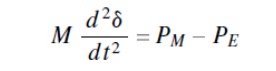
Where M = angular momentum of the synchronous generator
For small signal analysis,the equation is linearized as,
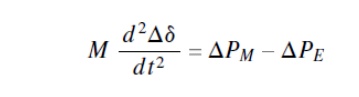
The mechanical-input power is assumed to be constant during the time of analysis; hence PM =0. The linearized-swing equation then becomes
The characteristic equation of the differential equation provides two roots:
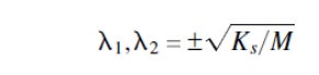
If the synchronizing torque Ks is positive, the resulting system is oscillatory with imaginary roots:
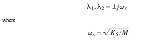
On the other hand, if the synchronizing torque KS is negative, the roots are real. A positive real root characterizes instability. The synchronizing-torque coefficient is now determined for both the uncompensated and SVC-compensated systems.
3. Steady State Power Transfer Capacity
Ø An SVC can be used to enhance the power-transfer capacity of a transmission line, which is also characterized as the steady-state power limit.
Ø Consider a single-machine infinite-bus (SMIB) system with an interconnecting lossless tie line having reactance X shown in Fig.
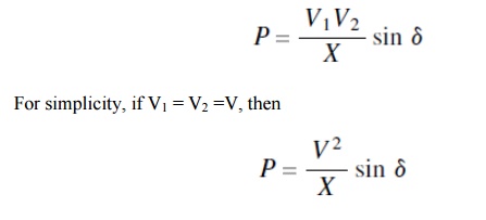
Ø Let the voltages of the synchronous generator and infinite bus be V1/–δ and V2/–δ, respectively. The power transferred from the synchronous machine to the infinite bus is expressed as
The SMIB system: (a) an uncompensated system (b) an SVC-compensated system
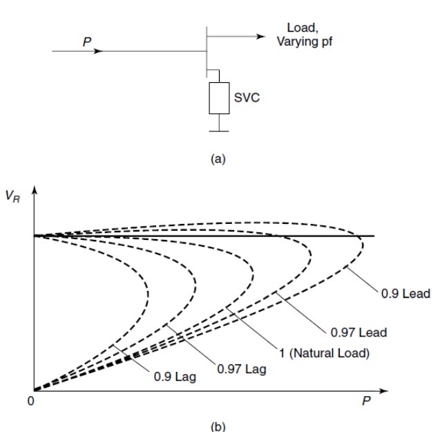
Ø The power thus varies as a sinusoidal function of the angular difference of the voltages at the synchronous machine and infinite bus, as depicted in Fig.
Ø The maximum steady-state power that can be transferred across the uncompensated line without SVC corresponds to δ = 900; it is given by
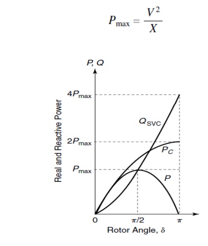
The variation of linear real-power flow and SVC reactive-power flow in a SMIB system
Ø Let the transmission line be compensated at its midpoint by an ideal SVC.
Ø The term ideal corresponds to an SVC with an unlimited reactive-power rating that can maintain the magnitude of the midpoint voltage constant for all real power flows across the transmission line.
Ø The SVC bus voltage is then given by Vm/–δ/ 2.The electrical power flow across the half-line section connecting the generator and the SVC is expressed as
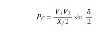
Ø The maximum transmittable power across the line is then given by
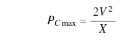
which is twice the maximum power transmitted in the uncompensated case and occurs at δ/ 2 =900.
Ø If the transmission line is divided into n equal sections, with an ideal SVC at each junction of these sections maintaining a constant-voltage magnitude (V), then the power transfer (P′c) of this line can be expressed theoretically by
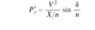
Ø The maximum power, P′c max, that can be transmitted along this line is nV2/ X. In other words, with n sections the power transfer can be increased n times that of the uncompensated line.
Ø It may be understood that this is only a theoretical limit, as the actual maximum power flow is restricted by the thermal limit of the transmission line.
Ø It can be shown that the reactive-power requirement, QSVC, of the midpoint SVC for the voltage stabilization is given by
Power angle curve of a SMIB systemLa) uncompensated (b) ideal midpoint SVC unlimited rating curve (c) fixed capacitor connected at its midpoint (d) midpoint SVC limited rating curve
Ø This curve is based on the corresponding equivalent reactance between the synchronous generator and the infinite bus.
Ø If an SVC incorporating a limited-rating capacitor as in the preceding text (QSVC _ 2Pmax) is connected at the line midpoint, it ensures voltage regulation until its capacitive output reaches its limit.
Ø In case the system voltage declines further, the SVC cannot provide any voltage support, and behaves as a fixed capacitor.
Ø Curve (d) represents the power-angle curve that shows this fixed-capacitor behavior and demonstrates that the realistic maximum power transfer will be much lower than the theoretical limit of 2Pmax if the SVC has a limited reactive-power rating.
4. Enhancement of Power System Damping
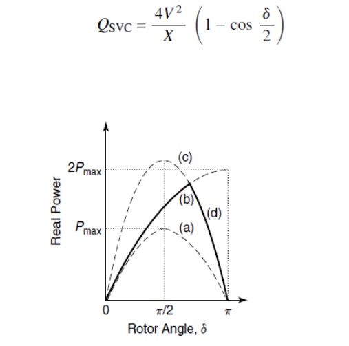
Ø The power-transfer capacity along a transmission corridor is limited by several factors; for example, the thermal limit, the steady-state stability limit, the transient-stability limit, and system damping.
Ø In certain situations, a power system may have inadequate—even negative— damping; therefore, a strong need arises to enhance the electrical damping of power systems to ensure stable, oscillation-free power transfer.
Ø A typical scenario of the magnitude of various limits, especially where damping plays a determining role , is depicted graphically in Fig. Oscillations in power systems are caused by various disturbances.
Ø If the system is not series-compensated, the typical range of oscillation frequencies extends from several tenths of 1 Hz to nearly 2 Hz.
Ø Several modes of oscillation may exist in a complex, interconnected power system.
Ø The behavior of generator oscillations is determined by the two torque components: the synchronizing torque anddamping torque.
Ø The synchronizing torque ensures that the rotor angles of different generators do not drift away following a large disturbance.
Ø In addition, the magnitude of the synchronizing torque determines the frequency of oscillation. Meanwhile, damping torque influences the decay time of oscillations.
Ø Even if a power system is stable, the oscillations may be sustained for a long period without adequate damping torque.
5. Prevention of Voltage Stability
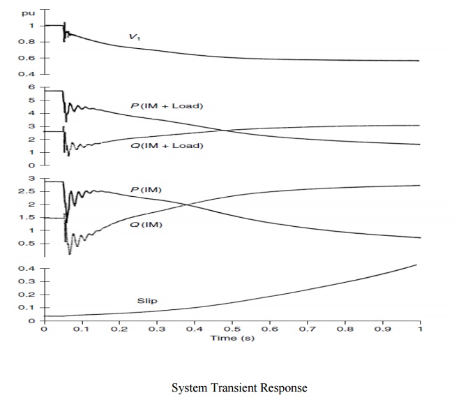
Ø Voltage instability is caused by the inadequacy of the power system to supply the reactive-power demand of certain loads, such as induction motors.
Ø A drop in the load voltage leads to an increased demand for reactive power that, if not met by the power system, leads to a further decline in the bus voltage. This decline eventually leads to a progressive yet rapid decline of voltage at that location, which may have a cascading effect on neighboring regions that causes a system voltage collapse.
5.1 Principle of SVC Control
Ø The voltage at a load bus supplied by a transmission line is dependent on the magnitude of the load, the load-power factor, and the impedance of the transmission line.
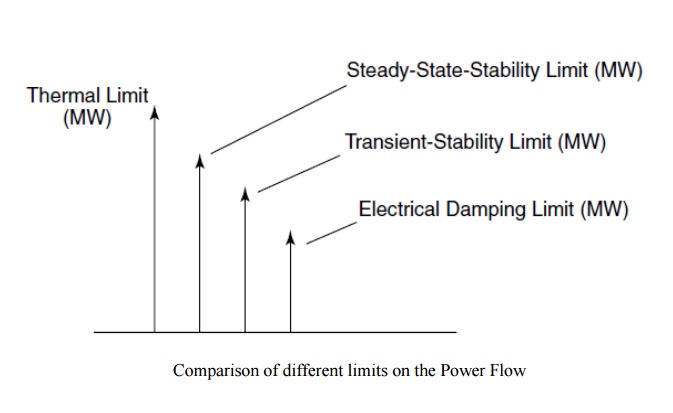
Ø Consider an SVC connected to a load bus, as shown in Fig. The load has a varying power factor and is fed by a lossless radial transmission line.
Ø The voltage profile at the load bus, which is situated at the receiver end of the transmission line, is depicted in Fig. For a given load-power factor, as the transmitted power is gradually increased, a maximum power limit is reached beyond which the voltage collapse takes place.
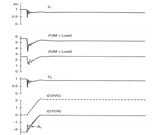
Ø In this typical system, if the combined power factor of the load and SVC is appropriately controlled through the reactive-power support from the SVC, a constant voltage of the receiving-end bus can be maintained with increasing magnitude of transmitted power, and voltage instability can be avoided.
(a) An SVC connected at the load bus by a radial transmission line supplying a load and
(b)the voltage profile at the receiving end of a loaded line with a varying power factor load.
5.2 Configuration and Design of the SVC Controller
Ø As the primary purpose of an SVC is voltage control, a PI-type voltage regulator is generally sufficient.
Ø The controller parameters are optimized using eigen value analysis to give fast, stable responses over the full range of expected network impedances and also without any adverse interactions with the power-system oscillation modes.
Ø In some situations, voltage dips may also be accompanied by system oscillations, as in the case of critical synchronous motor loads supplied by a distribution feeder.
Ø An auxiliary damping control may then need to be installed along with the voltage regulator.
5.3 Rating of an SVC
Ø Steady-state considerations determine the capacitive rating of an SVC. During a critical outage, the capacitive-reactive power needed to regulate the load voltage to a marginally stable level is selected as the capacitive range of SVC. Alternatively, once the critical bus that needs reactive-power support is identified, the SVC rating is chosen based on the capacitive-reactive power required to maintain the bus voltage at the minimum estimated SVC voltage-control range for the specified maximum loading condition or the voltage-collapse point .
Ø The collapse is indicated by the system Jacobian’s increasing singularity at that loading point and is obtained through load-flow studies.
Ø The inductance rating is chosen to be that which can restrict the dynamic overvoltages at the SVC bus to 10%. This is determined from transient studies for critical-load rejections.
Ø It is shown that the system loading cannot be increased beyond a maixmum value, irrespective of the size of the SVC connected at the critical bus. One means of obtaining the optimal SVC rating is maximization of a performance index,f p, where
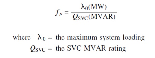
Ø The point of maximum f p corresponds to the maximum load increase at the minimum MVAR compensation level. This reactive-power level is chosen to be the optimal SVC rating.
Related Topics