Chapter: Automation, Production Systems, and Computer Integrated Manufacturing : Product Design and CAD/CAM in the Production System
Product Design and CAD
PRODUCT DESIGN AND CAD
Product
design is a critical function in the production system. The quality of the
product design (i.e.. how well the design department does its job) is probably
the single most important factor in determining the commercial success and
societal value of a product. If the product design is poor, no matter how well
it is manufactured, the product is very likely doomed to contribute little to
the wealth and wellbeing of the firm that produced it. If the product design is
good, there is still the question of whether the product can be produced at
sufficiently low cost to contribute to the company's profits and success. One
of the facts of life about product design is that a very significant portion of
the cost of the product is determined by its design. Design and manufacturing
cannot he separated in Ihe production system. They are bound together
functionally, technologically, and economically.
Let us
begin our discussion of product design by describing the general process of
design. We then examine how computers are used to augment and automate the
design process.
The Design Process
The
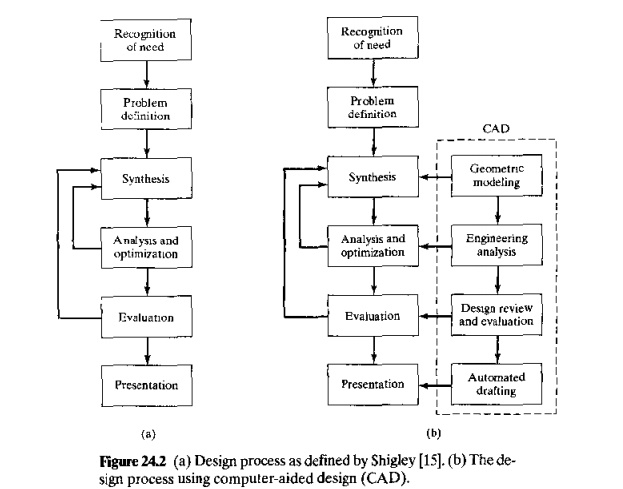
general process of design is characterized by Shigley as an iterative
process consisting of six phases: (1) recognition of need, (2) problem
definition, (3) synthesis, (4) analysis and optimization,(5) evaluation, and
(6) presentation. These six steps, and the iterative nature of the sequence in
which they are performed, are depicted in Figure 24.2(a).
Recognition
of need (1) involves the realization by someone that a problem exists for which
some corrective action can be taken in the form of a design solution. This
recognition might mean identifying some deficiency in a current machine design
by an engineer or perceiving of some new product opportunity by a salesperson.
Problem definition (2) involves a thorough specification of the item to be
designed. This specification includes the physical characteristics, function,
cost, quality, and operating performance.
Synthesis
(3) and analysis (4) are closely related and highly interactive in the design
process. Consider the development of a certain product design: Each of the subsystems
of the product must be conceptualized by the designer, analyzed, improved
through this analysis procedure, redesigned, analyzed again, and so on. The
process is repeated until the design has been optimized within the constraints
imposed on the designer. The individual components are then synthesized and
analyzed into the final product in a similar manner.
Evaluation
(5) is concerned with measuring the design against the specifications
established in the problem definition phase. This evaluation often requires the
fabrication and testing of a prototype model to assess operating performance,
quality, reliability, and other criteria. The final phase in the design
procedure is the presentation of the design. Presentation (6) is concerned with
documenting the design by means of drawings, material specifications, assembly
lists, and so on. In essence, documentation means that the design data base is
created.
Application
of Computers in Design
Computer-aided
design (CAD) is defined as any design activity that
involves the effective use of the computer to create,
modify, analyze, or document an engineering design. CAD is most commonly
associated with the use of an interactive computer graphics system, re
ferred 10
as a CAD system. The term CAD/CAM system is also used if it supports
manufacturing as well as design applications.
There are
several good reasons for using a CAD system to support the engineering design
function [l1J:
To increase the productivity of
the designer. This is accomplished by helping the designer to conceptualize the product and its components. In tum,
this helps reduce the time required bf the designer to synthesize, analyze, and
document the design.
To
improve the quality of Ihe design, The use of a CAD system with
appropriate hardware and software
capabilities permits the designer to do a more complete engineering analysis
and to consider a larger number and variety of design alternatives.
The
quality of the resulting design
is thereby improved.
To improve
design documentation. The graphical output of a CAD system results in better documentation of the design than
what is practical with manual drafting. The engineering drawings are superior,
and there is more standardization among the drawings, fewer drafting errors,
and greater legibility.
To create a manufacturing data base. In the
process of creating the documentation for
the product design (geometric specification of the product, dimensions of the
components, materials specifications, bill of materials, etc.), much of the
required data base to manufacture the product is also created.
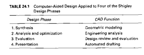
With
reference !O the six phases of design defined previously, a CAD system can
beneficially be used in four of the design phases, as indicated in Table 24.1
and Illustrated in Figure 24.2(b) as an overlay on the design process of
Shigley.
Geometric Modeling Geometric
modeling involves the use of a CAD system to
develop a mathematical description of the geometry of an object. The
mathematical description, called a geometric
model, is contained in computer memory. This pennits the user of the CAD
system to display an image of the model on a graphics terminal and toper-form
certain operations on the model. These operations include creating new
geometric models from basic building blocks available in the system, moving the
images around on the screen, zooming in on certain features of the image, and
so forth. These capabilities permit the designer to construct a model of a new
product (or Its components) or to modify an existing model.
There are
venous types of geometric models used in CAD. One classification distinguishes
between two dimensional (2D) and three dimensional (3D) models. Two dimensional
models are best utilized for design
problems in two dimensions, such as flat objects and layouts of buildings. In
the first CAD systems developed in the early 1970s, 2·0systems were used
principally as automated drafting systems. They were often used for 3D objects,
and it was left to the designer or draftsman to properly construct the various
views of the object. Three dimensional CAD systems are capable of modeling an
object in three dimensions. The operations and transformations on the model are
done by the system in three dimensions according to user instructions. This is
helpful in conceptualizing the object since the true 3D model can be displayed in various views and from different
angles.
Geometric
models in CAD can also be classified as being either wireframe models or solid
models. A wireframe model uses inter-connecting lines (straight line segments)
to depict the object as illustrated in Figure 24.3(a).Wireframe models of
complicated geometries can become somewhat confusing because all ofthe lines
depicting the shape of the object are usually shown, even the lines
representing the other side of the object. Techniques
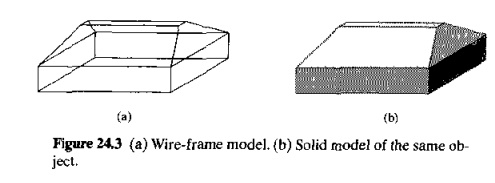
are
available for removing these so-called hidden lines, but even with this
improvement, wireframe representation is still often inadequate. Solid models
are a more recent development in geometric modeling. In solid modeling, Figure
24.3(b),an object is modeled in solid three dimensions, providing the user with
a vision of the object very much like it would be seen in real life. More
important for engineering purposes, the geometric model is stored in the CAD
system as a 3D solid model. thus providing a more accurate representation of
the object. This is useful for calculating mass properties, in assembly to
perform interference checking between mating components, and in other
engineering calculations.
Finally,
two other features in CAD system models are color and animation. Some CAD
systems have color capability in addition to black-and-white. The value of
color is largely to enhance {he ability of the user to visualize the object on
the graphics screen. For example, the various components of an assembly can be
displayed in different colors, thereby permitting the parts to be more readily
distinguished. Animation capability permits the operation of mechanisms and
other moving objects to be displayed on the graphics monitor.
Engineering
Analysis. After a particular design alternative has been developed, some form
of engineering analysis often must be performed as part of the design process.
The analysis may take the form of stress-strain calculations, heat transfer
analysis, or dynamic simulation. The computation are often complex and time
consuming, and before the advent of the digital computer, these analyses were
usually greatly simplified or even omitted in the design procedure. The
availability of software for engineering analysis on a CAD system greatly
increases the designer's ability and willingness. to perform a more thorough
analysis of a proposed design. The term computer-aided
engineering (CAE) is often used for engineering analyses performed by
computer. Examples of engineering analysis software in common use on CAD
systems include:
Mass
properties analysis, which involves the computation of such features of
a solid object as its volume, surface
area, weight, and center of gravity. It is especially applicable in mechanical
design. Prior to CAD, determination of these properties often required
painstaking and time consuming calculations by the designer.
Interference
checking. This CAD software examines 2D geometric models consisting of multiple
components to identify interferences between the components. It is useful in
analyzing mechanical assemblies, chemical plants, and similar multi component
designs
Tolerance
analysis. Software for analyzing the specified tolerances of a product'S components is used for the following
functions: (1) to assess how the tolerances may affect the product's function
and performance, (2) to determine how tolerances may influence the ease or
difficulty of assembling the product.and (3) to assess how variations in
component dimensions may affect the overall size of the assembly.
Finite element analysis. Software
for finite element analysis (FEA), also known as finite element modeling (FEM). is available for use on CAD systems
to aid in stress-strain, heat transfer, fluid flow, and other engineering
computations, Finite element analysis is a numerical analysis technique for
determining approximate solutions to physical problems described by
differential equations that are very difficult or impossible to solve. In FEA.
the physical object is modeled by an assemblage of discrete interconnected
nodes (finite elements), and the variable of interest (e.g., stress, strain,
temperature) in each node can be described by relatively simple mathematic
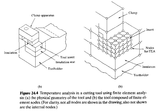
Figure
24.4 Temperature analysis in a cutting tool using finite element analysis: (a)
the physical geometry of the tool and (b) the tool composed of finite element
nodes. (For clarity. not all nodes are shown in the drawing; also not shown are
the internal nodes)
cal
equations, By solving the equations for each node. the distribution of values
of the variable throughout the physical object is determined. Figure 24.4
illustrates a finite element model to analyze temperatures in a cutting tool.
Kinematic
and dynamic analysis. Kinematic analysis involves the study of the
operation of mechanical linkages to analyze their motions. A typical kinematic
analysis consists of specifying the motion of one or more driving members of
the subject linkage, and the resulting motions of the other links are
determined by the analysis package. Dynamic analysis extends kinematic analysts
by including the effects of the mass of each linkage member and the resulting
acceleration forces as well as any externally applied forces
Discrete-event
simulation. This type of simulation is used to model complex
operational systems, such as a manufacturing cell or a material handling
system, as events occur at discrete moments in time and affect the status and
performance of the system. For example, discrete events in the operation of a
manufacturing cell include parts arriving for processing or a machine breakdown
in the cell. Measures of the status and performance include whether a given
machine in the cell is idle or busy and the overall production rate of the
cell. Current discrete-event simulation software usually includes an animated
graphics capability that enhances visualization of the system's operation.
Design Evaluation and Review. Design
evaluation and review procedures can be augmented
by CAD. Some of the CAD features that
are helpful in evaluating: and reviewing a proposed design include:
•Automatic dimensioning routines
that determine precise distance measures between surfaces on the geometric model identified hy the user.
Error
checking. This term refers 10 CAD algorithms that are used to review
the accuracy and consistency of dimensions and tolerances and to assess whether
the proper design documentation format has been followed
Animation
of discrete-event simulation solutions. Discrete event simulation
was described above in the context of engineering analysis. Displaying the
solution of the discrete-event simulation in animated graphic, is a helpful
means of presenting and evaluating the solution. Input parameters, probability
distributions, and other factors can he changed to assess their effect on the
performance of the system being modeled
Plant
layout design scores. A number of software packages are available for
facilities design. that is, designing the floor layout and physical arrangement
of equipment in a facility. Some of these packages provide one or more
numerical scores for each plant layout design, which allow the user to assess The
merits of the alternative with respect to material flow, closeness ratings. and
similar factors.
The
traditional procedure in designing a new product includes fabrication of a
prototype before approval and release of the product for production The
prototype serves as the "acid test" of the design, permitting the designer
and others to see. feel, operate, and test the product for any last-minute
changes or enhancements of the design. The problem with building a prototype is
that it is traditionally very time consuming; in some cases, months are
required to make and assemble all of the parts. Motivated by the need to reduce
this lead time for building the prototype. several new approaches have been
developed that rely on the usc of the geometric model of the product residing
in the CAD data file. We mention two of these approaches here: (1) rapid
prototyping and (2) virtual prototyping,
Rapid prototyping is a
general term applied to a family of fabrication technologies that allow engineering prototypes of
solid parts to be made in minimum lead time [12J. The common feature of the
rapid prototyping processes is that they fabricate the part directly from the
CAD geometric model. This is usually done by dividing the solid object into a
series of layers of small thickness and then defining the area shape of each
layer. For example, a vertical cone would be divided into a series of circular
layers, each circle becoming smaller and smaller as the vertex of the cone is
approached. The rapid prototyping processes then fabricate the object by
starting at the base and building each layer on top of the preceding layer to
approximate the solid shape. The fidelity of the approximation depends on the
thickness of each layer. As layer thickness decreases, accuracy increases.
There are a variety of layer-building
processes used in rapid prototyping. The most common process, called stereollthography, uses a photosensitive
liquid polymer that cures (solidifies) when Subjected to intense light. Curing
of the polymer is accomplished using a moving laser beam whose path for each
layer is controlled by means of the CAD model. By hardening each layer, one on
top of the preceding, a solid polymer prototype of the part is built.
Virtual prototyping. based on
virtual reality technology, involves the use of the CAD geometric model to construct a digital mockup of the product,
enabling the designer and others to obtain the sensation of the real physical
product without actually building the physical prototype. Virtual prototyping
has been used in the automotive industry to evaluate new car style designs. The
observer of the virtual prototype is able to assess the appearance of the new
design even though no physical model is on display. Other applications of
virtual prototyping include checking the feasibility of assembly operations,
for example, parts mating, access and clearance of parts during assembly, and
assembly sequence.
Automated
Drafting. The fourth area where CAD is useful (step 6 in the design process)
is presentation and documentation. CAD systems can be used as automated
drafting machines to prepare highly accurate engineering drawings quickly. It
is estimated that a CAD system increases productivity in the drafting function
by about fivefold over manual preparation of drawings
Related Topics