Chapter: Power Electronics : Inverters
Inverters
INVERTERS
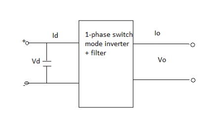
The device that converts dc power into ac power at desired output voltage and frequency is called an inverter.
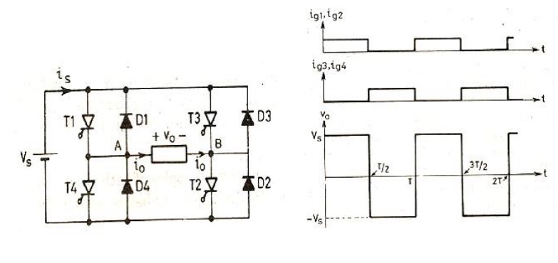
1. Single phase voltage source inverters
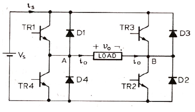
2. Single phase full bridge inverter
3. Types Of Inverter
Inverters are of the two types
1) VSI
2) CSI
3.1 Pulse width model
The VSI can be further divided into general 3 categories: 1.Pulse width modulated inverters
2.Square wave inverters
3.Single phase inverter with voltage cancellation
3.2.1 Pulse width modulated inverters
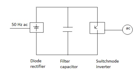
The input dc voltage is of constant magnitude . The diode rectifier is used to rectify the line voltage. The inverter control the magnitude and frequency of the ac output voltage. This is achieved by PWM technique of inverter switches and this is called PWM inverters. The sinusoidal PWM technique is one of the PWM technique to shape the output voltage to as close as sinusoidal output.
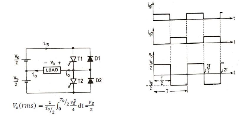
Basic concepts of switch mode inverter
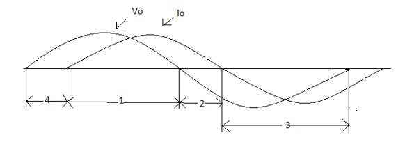
During interval 1 v0 and i0 both are positive
During interval 3 v0 and i0 both are negative
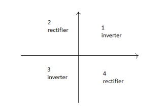
Therefore during 1 and 3 the instantaneous power flow is from dc side to corresponding to inverter mode of operation.
In contrast during interval 2 and 4 v0 and i0 are of opposite sign i.e. power flows from ac side to dc side corresponding to rectifier mode of operation.
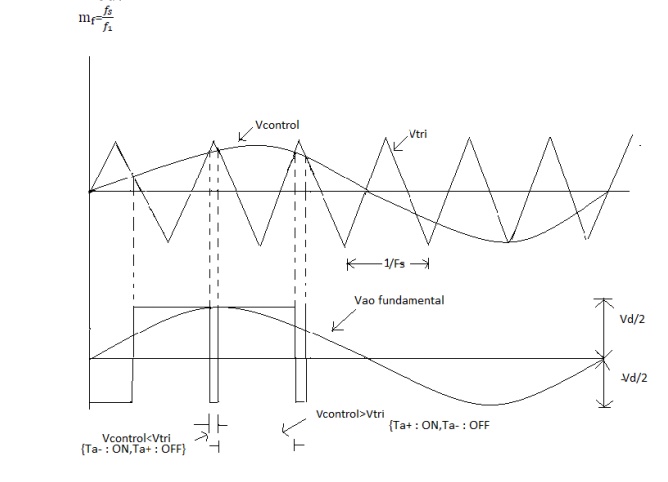
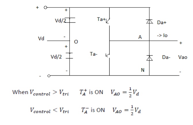
3.2.2 Pulse width modulated switching scheme
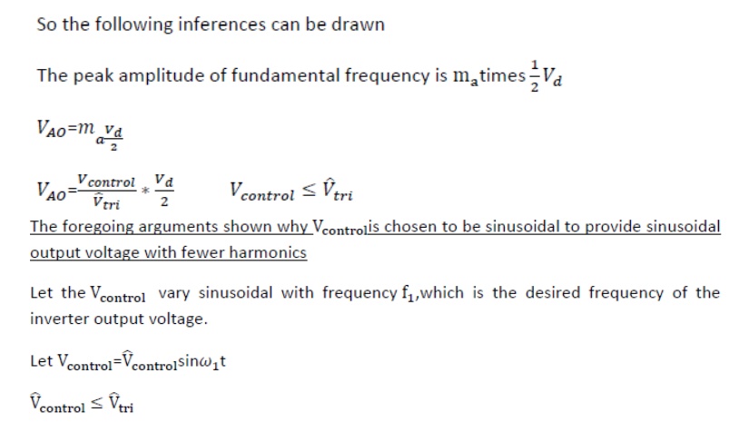
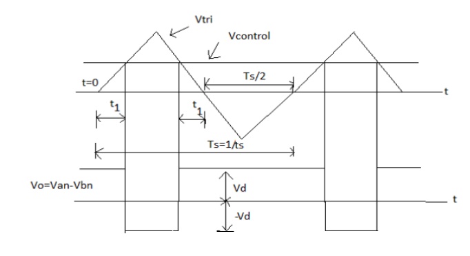
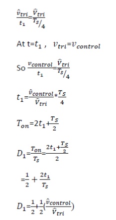
We require the inverter output to be sinusoidal with magnitude and frequency controllable. In order to produce sinusoidal output voltage at desired frequency a sinusoidal control signal at desired frequency is compared with a triangular waveform as show. The frequency of the triangular waveform established the inverter switching frequency. The triangular waveform is called carrier waveform. The triangular waveform establishes switching frequency , which establishes with which the inverter switches are applied.
The control signal has frequency fs and is used to modulate the switch duty ratio. f1 is the desired fundamental frequency of the output voltage.
The amplitude modulation ratio ma is defined as
Ma = Vcontrol/Vtri
V control is the peak amplitude of control
Signal Vtri peak amplitude of triangular signal.
The frequency modulation mf
3.2.3 Three phase inverter
When three single-phase inverters are connected in parallel a three phase inverter is formed.
The gating signal has to be displaced by 1200 with respect to each other so as achieve three phase balanced voltages.
A 3-phase output can be achieved from a configuration of six transistors and six diodes.
Two type of control signal can be applied to transistors, they are such as 180 or 120 conduction.
4. 180-degree conduction
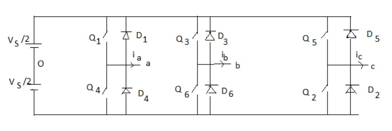
When When O1 is switched on, terminal a is connected to the positive terminal of dc input voltage.
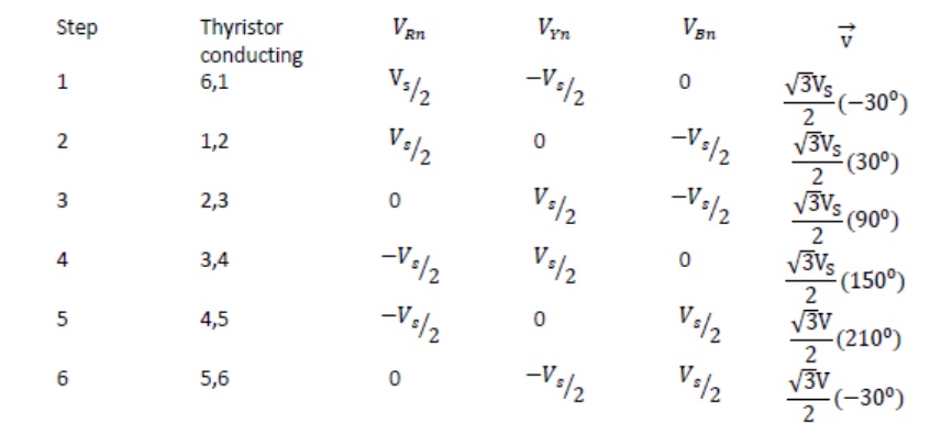
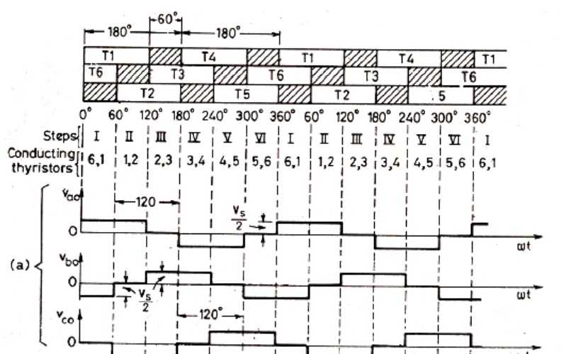
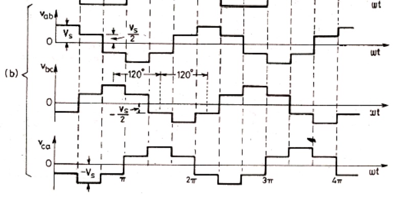
When O4 is switched on terminal a is brought to negative terminal of the dc source. There are 6 modes of operation is a cycle and the duration of each mode is 600.
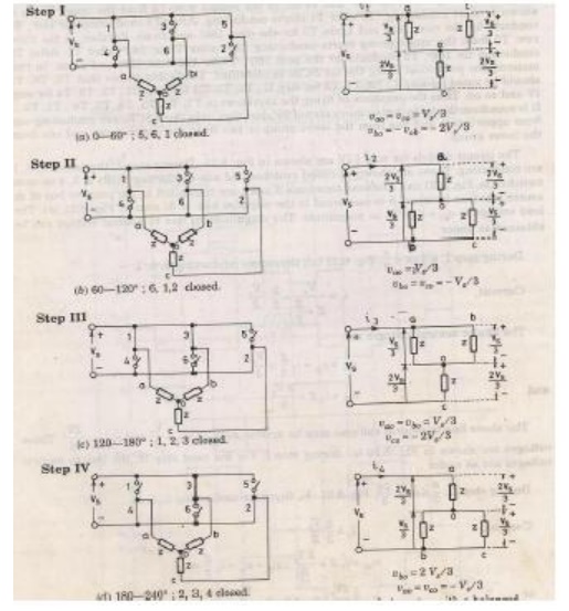
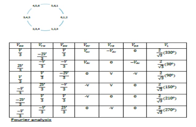
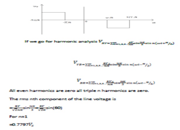
The conduction sequence of transistors is 123,234,345,456,561,612. The gating signals are shifted from each other by 600 to get 3-ϕ balanced voltages.Switching states for the three phase voltage inverters
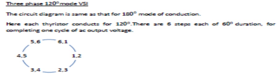
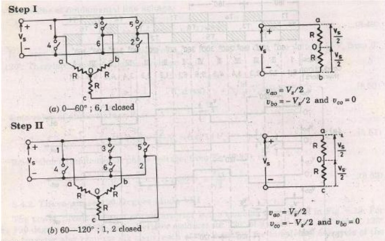
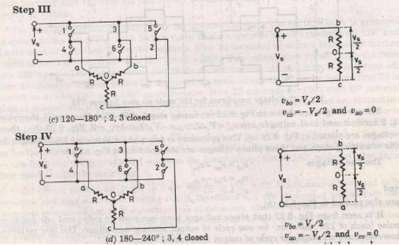
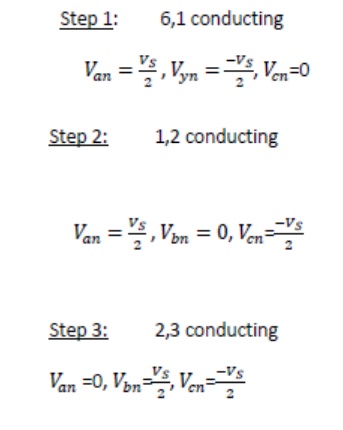
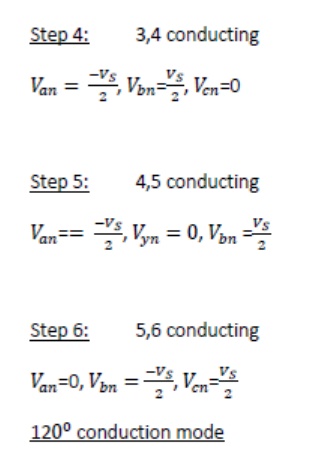
5. 120-degree conduction