Chapter: Mechanical : Kinematics of Machinery : Friction in the Machine Elements
Friction in the Machine Elements
FRICTIONIN THE MACHINE ELEMENTS
1 Surface contacts:
·
Basic laws of friction
·
Pivot and collar, introducti on and types.
·
Problem on flat pivot, Problems on conical pivot.
Friction
Friction is
a measure of how hard it is to slide one object over another. Take a look at the
figure below. Both of the blocks are made
from the same material, but one is heavier. I think we all know which one will be
harder for the bulldozer to push.
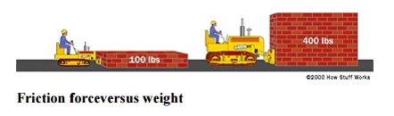
Friction force versus weight
To
understand why this is, let's take a
close look at one of the blocks and the
table:
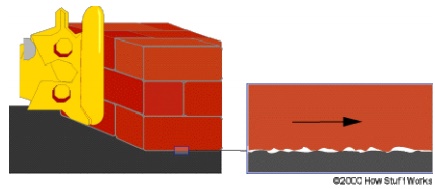
Because friction exists at the microscopic level,
the amount of force it takes to move a given block is proportional to that
block's weight.
Even though
the blocks look smooth to the naked eye, they are actually quite rough at the
microscopic level. When you set the block down on the table, the little peaks
and valleys get squished together, and some of them may actually weld together.
The weight of the heavier block causes it to squish together more, so it is
even harder to slide. Different materials have different microscopic
structures; for instance, it is harder to slide rubber against rubber than it
is to slide steel against steel. The type of material determines the
coefficient of friction, the ratio of the force required to slide the block to
the block's weight. If the coefficient were 1.0 in our example, then it would
take 100 pounds of force to slide the 100-pound (45 kg) block, or 400 pounds (180
kg) of force to slide the 400-pound block. If the coefficient were 0.1, then it
would take 10 pounds of force to slide to the 100-pound block or 40 pounds of
force to slide the 400-pound block.
So the
amount of force it takes to move a given block is proportional to that block's
weight. The more weight, the more force required. This concept applies for
devices like brakes and clutches, where a pad is pressed against a spinning
disc. The more force that presses on the pad, the greater the stopping force.
FRICTION
Dry friction – Friction in screw jack – Pivot and
collar friction - Plate clutches - Belt and rope drives - Block brakes, band
brakes.
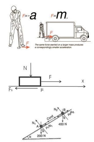
Friction:
The opposing force which acts in the opposite
direction of the movement of the upper block is called the force of friction or
friction.
Types or friction:
1. Static
friction: It is experienced by a body, when at rest.
2. Dynamic
friction: It is friction experienced by a body when in motion.
a. Sliding
friction: It is friction experienced by a body when it slides over another
body.
b. Rolling
friction: It is friction experienced between the surfaces which the balls or
rollers interposed between them.
c. Pivot
friction: It is the friction experienced by a body due to motion of rotation.
Further
classified
1. Friction
between unlubricated surfaces
2. Friction
between lubricated surfaces. Laws of dry or solid friction:
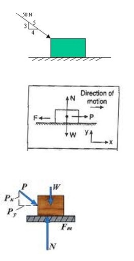
Ø The force
of friction directly proportional to the normal load between the surfaces.
Ø The force
of friction is independent of the area of the contact surface for a given
normal load.
Ø The force
of friction depends upon material which the contact surfaces or made.
Ø The force
of friction is independent of the velocity of sliding of one body relative to
other body.
Coefficient
of friction (µ):
It is as
the ratio the limiting friction (F) to the normal reaction (RN) between the two
bodies.
µ= F/ RN
Angle of
friction:
It may be defined as the angle which the resultant
reaction R makes with normal reactions
tan ϕ= F/ RN
2 Friction drives:
3 Friction in screw threads:
·
Friction in screw and nut
·
Friction in screw jack
·
Problems in screw jack
Screwjack:
The screw
jack is a device lifting loads. For lifting heavy loads by applying a
comparatively smaller effort at its handle. The principle on which a screw jack
works in a smaller to that of an inclined plane.
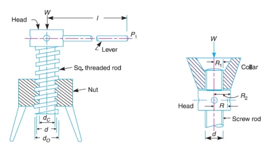
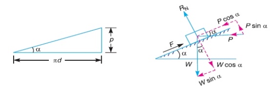
1. Torque required lifting the load by a screw jack
Let p=pitch of the screw
d =mean
diameter of the screw
α= helix
angle
P= effort
applied at the circumference of the screw to lift the load
W=load to
be lifted
µ=coefficient
of the friction
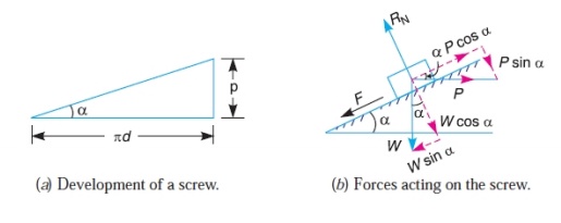
tan
α=p/Πd
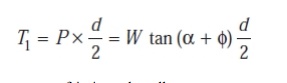
Torque
required overcoming friction between the screw and nut
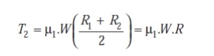
The
torque required to overcome friction at the collar
Total
Torque required overcoming friction
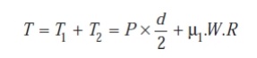
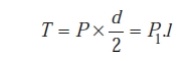
If an P1
is applied at the end of a lever of arm l, then the total torque required to
overcome friction must be equal to the torque applied at the end of the lever
2. Torque required lower the load by a screw jack
Let p=pitch of the screw
d =mean
diameter of the screw
α= helix
angle
P= effort
applied at the circumference of the screw to lift the load
W=load to
be lifted
µ=coefficient
of the friction
tan
α=p/Πd
Torque
required overcoming friction between the screw and nut
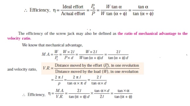
Efficiency
of the screw jack:
The
efficiency of the screw jack may b defined as the ratio between the ideal efforts
to actual effort.
Self
locking and over hauling of screws
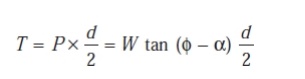
Torque
required to lower the load
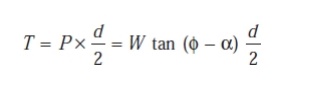
In the above expressions ,if ϕ< α ,then the torque required
to lower the load will be negative ,the load will start moving downward without
application of force, such a condition is known as overhauling of screw.
If ϕ> α ,then the torque required
to lower the load will be positive ,indicating that an efforts applied lower
the load , such a condition is known as self locking of screw
4 Clutch
For other uses, see Clutch (disambiguation).
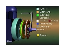
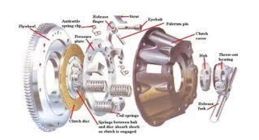
Clutch for a drive shaft: The clutch disc (center) spins with the flywheel (left).
To disengage, the lever is pulled
(black arrow), causing a white pressure plate (right) to disengage the green
clutch disc from turning the drive shaft, which turns within the thrust-bearing
ring of the lever. Never will all 3 rings connect, with no gaps.
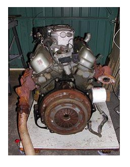
Rear side
of a Ford V6 engine, looking at the clutch housing on the flywheel
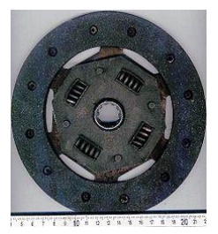
Single,
dry, clutch friction disc. The splined hub is
attached to the disc with springs to damp chatter.
A clutch is a mechanical device, by
convention understood to be rotating, which provides driving force to another
mechanism when required, typically by connecting the driven mechanism to the
driving mechanism. Clutches and brakes are similar; if the driven member of a
clutch is fixed to the mechanism frame, it serves as a brake.
Clutches are useful in devices that have two rotating shafts. In these devices, one shaft is typically attached to a motor or other power unit (the driving member), and the other shaft (the driven member) provides output power for work to be done. In a drill, for instance, one shaft is driven by a motor, and the other drives a drill chuck. The clutch connects the two shafts so that they can either be locked together and spin at the same speed (engaged), or be decoupled and spin at different speeds (disengaged).
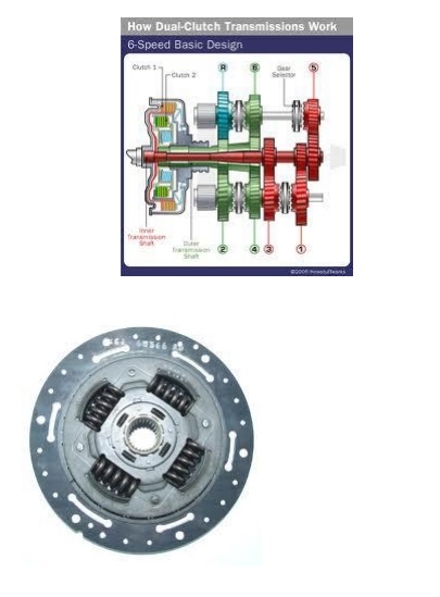
Multiple plate clutch
This type
of clutch has several driving members interleaved with several driven members.
It is used in race cars including F1, Indy car, World rally and even most club
racing, motorcycles, automatic transmissions and in
some diesel locomotives with
mechanical transmissions. It is also used in some electronically controlled
all-wheel drive systems.
Vehicular
There are
different designs of vehicle clutch but most are based on one or more friction
discs pressed tightly together or against a flywheel using springs. The
friction material varies in composition depending on many considerations such
as whether the clutch is "dry" or "wet". Friction discs
once contained asbestos but this has been largely eliminated. Clutches found in
heavy duty applications such as trucks and competition cars use ceramic
clutches that have a greatly increased friction coefficient. However, these
have a "grabby" action generally considered unsuitable for passenger
cars. The spring pressure is released when the clutch pedal is depressed thus
either pushing or pulling the diaphragm of the pressure plate, depending on
type. However, raising the engine speed too high while engaging the clutch
causes excessive clutch plate wear. Engaging the clutch abruptly when the
engine is turning at high speed causes a harsh, jerky start. This kind of start
is necessary and desirable in drag racing and other competitions, where speed
is more important than comfort.
5.4.1 Friction clutches:
Single
plate clutches and Multi-plate clutche Uniform wear theory and Uniform pressure
theory Problems in clutches
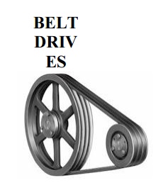
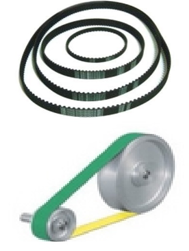
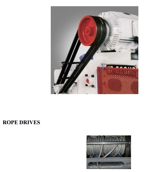
5 BELT
The belt or
ropes are used to transmit power from one shaft to another shaft by means of pulleys
which rotate at the same speed or at different speed.
Types of belt
drives.
1. Light
drives: belt speed upto10m/s
2. Medium
drives: speed 10m/s to22m/s
3. Heavy
drives :Speed ove r22m/s
1Types of belt
1.Flat
belt
2.V- belt
3.Circular
belt or rope
Type of
flat belt drives
Open belt
drive
Cross
belt drive
Quarter
turn belt drive
Belt
drive with idler pulley
Velocity
of belt drive
It is the
ratio between the velocies of the driver and follower or driven.
d1 = diameter
of the driver
d2 = diameter
of the follower
N1 = Speed
of the driver r.p.m
N2 = Speed
of the driven r.p.m
Let r1
and r1 = Radii
of the larger or smaller pulleys
x
=Distance between the centres of the two pulleys
L = Total length of the belt.
Length of
an open belt drive
Length of
the cross belt drive.
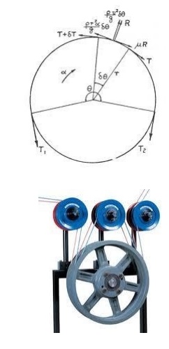
Power
transmitted by a belt
T1
and T2 = Tensions in the tight and slack side of
the belt respectively N
r1 and r1 = Radii
of the larger or smaller pulleys
v =Velocity of the belt m/s
Power = (T1-T2)v
W
Belt and rope drives:
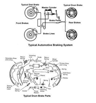
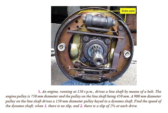
6 Friction aspects in Brakes:
BRAKES
Related Topics