Chapter: 9th Science : Magnetism and Electromagnetism
Electric generator
Electric generator
An alternating current
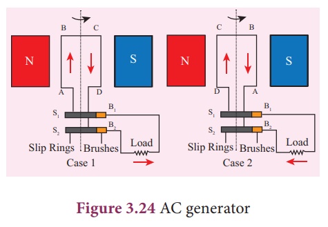
(AC) generator, as shown in Figure 3.24, consists of a rotating rectangular
coil ABCD called armature placed between the two poles of a permanent magnet.
The two ends of this coil are connected to the two slip rings S1 and
S2. The inner sides of these rings are insulated. Two conducting
stationary brushes B1 and B2 are kept separately on the
rings S1 and S2 respectively. The two rings S1
and S2 are internally attached to an axle. The axle may be
mechanically rotated from outside to rotate the coil inside the magnetic field.
Outer ends of the two brushes are connected to the external circuit.

When the coil is
rotated, the magnetic ux linked with the coil changes. is change in magnetic ux
will lead to generation of induced current. The direction of the induced
current, as given by Fleming’s Right Hand Rule, is along ABCD in the coil and
in the outer circuit it ows from B2 to B1. During the
second half of rotation, the direction of current is along DCBA in the coil and
in the outer circuit it ows from B1 to B2. As the rotation of the coil
continues, the induced current in the external circuit is changing its
direction for every half a rotation of the coil.

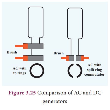
To get a direct current
(DC), a split ring type commutator must be used. With this arrangement, one
brush is at all times in contact with the arm moving up in the field while the
other is in contact with the arm moving down. Thus a unidirectional current is
produced. The generator is thus called a DC generator (Figure 3.25).
Related Topics