Chapter:
Computer Aided Design
Computer Aided Design
CAD is the intersection of Computer Graphics, Geometric modeling and Design tools (Fig.1.4.). The concepts of computer graphics and geometric modeling and must be used innovatively to serve the design process.
CAD is the function of computer systems to support in the creation, modification, analysis, or optimization of a design.
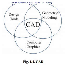
Fig. 1.4. CAD
CAD software for design uses either vector-based graphics to explain the objects of traditional drafting, or may also develop raster graphics showing the overall look of designed objects. During the manual drafting of engineering drawings, the output of CAD must convey information, like dimensions, materials, processes, and tolerances.
CAD is a significant industrial art used in many purposes, including industrial and architectural design, shipbuilding, automotive, and aerospace industries, and many more. CAD is also extensively used to create computer animation for special effects in movies, and technical manuals, frequently called as Digital Content Creation.
CAD software packages provide the designer with a multi window environment with animation which is regularly used in Digital Content Creation. The animations using wire frame modeling helps the designer to see into the interior of object and to observe the behaviors of the inner components of the assembly during the motion.
CAD Technology
Initially software for CAD systems was developed with computer languages such
as FORTRAN but with the development of object-oriented programming methods this has completely changed. Classic modern parametric attribute based modeler and freeform surface systems are developing around a number of key ‘C’modules.
A CAD system can be seen as develop from the interaction of a Graphical User Interface (GUI) with NURBS geometry and Boundary representation data through a kernel for geometric modeling. A geometry constraint engine may also be employed to organize the associative relationships between
components in an assembly.
Unexpected facilities of these relationships have led to a new form of prototyping called digital prototyping. In difference to physical prototypes, which involve manufacturing time in the design. CAD models can be created by a computer after the physical prototype has been scanned using an CT scanning device. Based on the nature of the business, digital or physical prototypes can be primarily
selected according to specific requirements.
Currently, no special hardware is required for CAD software. However, some special CAD systems can do graphically and computationally intensive tasks, so a higher end graphics card, high speed CPUs may be suggested. CAD systems exist for all the major platforms and some packages even
perform multiple platforms.
The human-machine interface is generally through a mouse but can also be using a
digitizing graphics tablet. Handling of the view of the part on the screen is also sometimes done with the help of a Space mouse or Space Ball. Special CAD systems also support stereoscopic glasses for viewing the 3D objects.
The CAD tools are mainly using for graphics applications and modeling. Aids such a color, grids, geometric modifiers and group facilitate structural geometric models. Visualization is achieved through shaded components and animation which focus design conceptualization, communication and interference detection. FEM packages provide optimization in shape and structure. Adding tolerances, tolerance analysis and investigating the effect of manufacturing on the design can perform by utilizing CAD tools (Table 1.2).
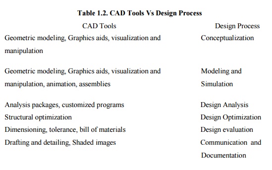
Table 1.2. CAD Tools Vs Design Process
CAD Tools : Design Process
Geometric modeling, Graphics aids, visualization and manipulation : Conceptualization
Geometric modeling, Graphics aids, visualization and Modeling and manipulation, animation, assemblies : Simulation
Analysis packages, customized programs : Design Analysis
Structural optimization : Design Optimization
Dimensioning, tolerance, bill of materials : Design evaluation
Drafting and detailing, Shaded images : Communication and Documentation
Uses of CAD
CAD is one of the tools used by designers and engineers and is used in different ways depending on the profession of the customer and the type of software.
CAD is one of the Digital Product Development activities within the Product Lifecycle Management practices with other tools, which are either integrated modules or individual, such as:
· Computer Aided engineering (CAE) and Finite Element Analysis (FEA)
· Computer Aided Manufacturing (CAM)
· Realistic Rendering and Simulation.
· Product Data Management (PDM).
CAD is also used for the development of photo simulations that are frequently necessary in the preparation of Environmental Impact Reports, in which proposed CAD buildings are superimposed into photographs of existing situation to represent what that conditions will be like, where the proposed services are allowed to be built.
Parameters and constraints can be used to get the size, shape, and other properties of the modeling elements. The features of the CAD system can be used for the several tools for measurement such as yield strength, tensile strength and electrical or electro-magnetic properties.
Computer architecture is a pattern describing how a group of software and hardware technology standards relate to form a computer system. In general, computer architecture refers to how a computer is designed and what technologies it is compatible with. Computer architecture is likened to the art of shaping the needs of the technology, and developing a logical design and standards based on needs.
In CAD, Computer architecture is a set of disciplines that explains the functionality, the organization and the introduction of computer systems; that is, it describes the capabilities of a computer and its programming method in a summary way, and how the internal organization of the system is designed and executed to meet the specified facilities. Computer architecture engages different aspects, including instruction set architecture design, logic design, and implementation. The implementation includes Integrated Circuit Design, Power, and Cooling. Optimization of the design needs expertise with Compilers, Operating Systems and Packaging.
Instruction set architecture
An instruction set architecture is the interface between the software and hardware and also can be observed as the programmer's view of the machine. Computers do not understand high level languages, if any, language elements that translate directly into a machine's native op codes.